Cooler for cooling electric part

a technology for electric parts and coolers, which is applied in the direction of cooling/ventilation/heating modifications, semiconductor/solid-state device details, cooling/ventilation/heating modifications, etc., can solve the problems of reducing affecting the cooling performance of the cooler, etc., to achieve high cooling performance

Active Publication Date: 2005-02-10
DENSO CORP
View PDF6 Cites 46 Cited by
  • Summary
  • Abstract
  • Description
  • Claims
  • Application Information

AI Technical Summary

Benefits of technology

[0009] In view of the above-described problem, it is an object of the present inventi

Problems solved by technology

Thus, a manufacturing cost of the cooler 9 becomes larger.
However, this construction may decrease a cooling performance of the cooler 9.
In this case, when the thickness of each module 92 is different from each other, the variation in the stacking directio

Method used


Image

  • Cooler for cooling electric part
  • Cooler for cooling electric part
  • Cooler for cooling electric part

Examples


first embodiment

[0039] (First Embodiment)

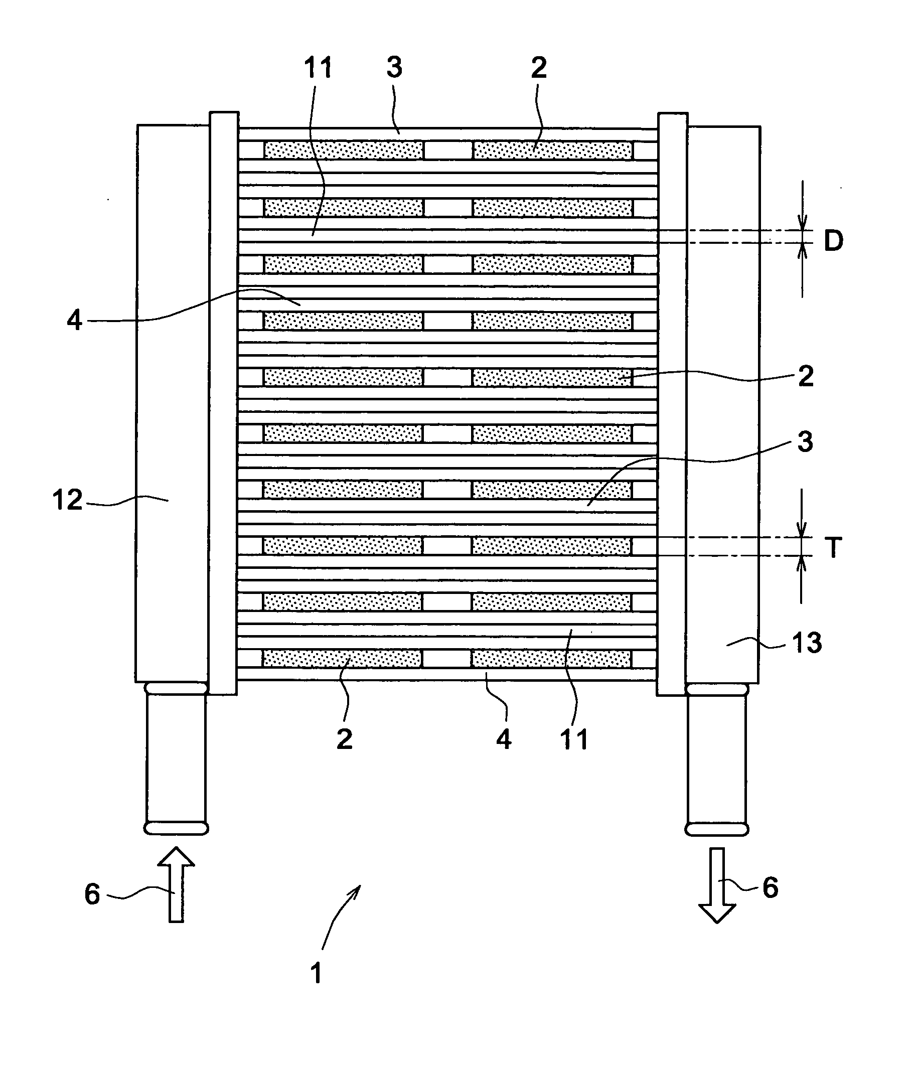
[0040] A cooler 1 according to a first embodiment of the present invention is shown in FIG. 1. The cooler 1 cools multiple electric parts 2 on both sides thereof. The cooler 1 includes a cooling unit 4 having a pair of cooling tubes 3 for passing coolant 6 therethrough. The cooling tube 3 has a flat shape. A pair of the cooling tube 3 sandwiches two electric parts 2 disposed in parallel. Multiple cooling units 4 are stacked in a stacking direction, which is parallel to a thickness direction of the cooling tube 3. A clearance 11 is disposed between the neighboring cooling units 4. The clearance 11 is disposed between one cooling tube 3 and the other cooling tube 3. Specifically, the clearance 11 is disposed between one side of the one cooling tube 3, which is opposite to the electric part 2, and another one side of the other cooling tube 3, which is opposite to the other electric part 2. The thickness D, i.e., the width of the clearance 11 is smaller than the...

second embodiment

[0050] (Second Embodiment)

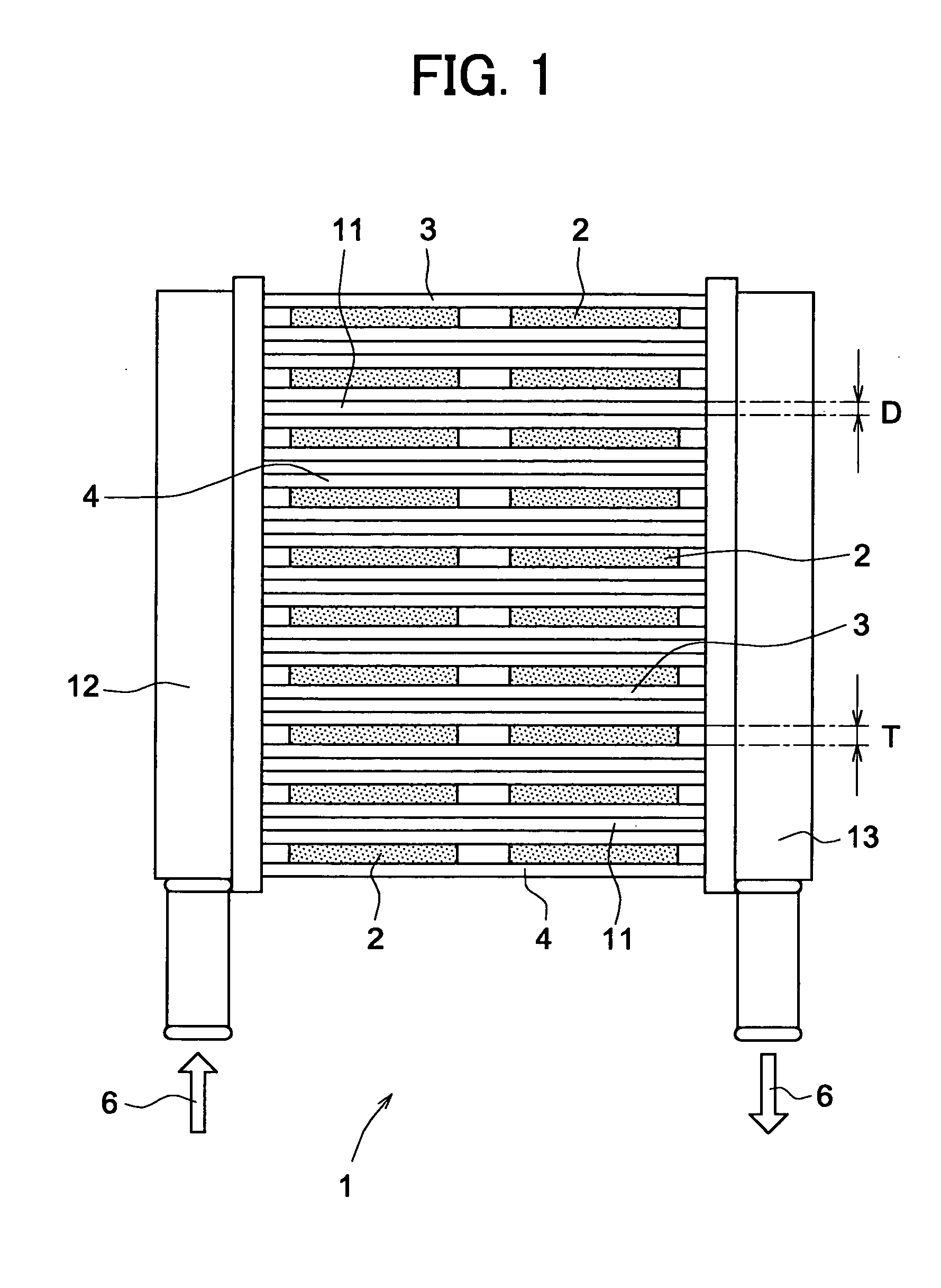
[0051] A cooler 1 according to a second embodiment of the present invention is shown in FIG. 2. The cooler 1 includes a heat insulation member 14 inserted into the clearance 11. The heat insulation member 14 is made of resin having low heat conductivity and elasticity such as silicone plate, fluorine resin plate, resin filler, or rubber plate.

[0052] In this case, the heat generated in one electric part 2 is prevented from transferring to another electric part 2. Therefore, the cooler 1 has high cooling performance. Since the heat insulation member 14 has the elasticity, the different thickness T of the electric part 2 can be absorbed into each cooling unit 4, i.e., the heat insulation member 14. Thus, the electric part 2 is precisely sandwiched and fixed by the cooling tube 3. Accordingly, the cooling performance of the cooler 1 is improved.

third embodiment

[0053] (Third Embodiment)

[0054] A cooler 1 according to a third embodiment of the present invention is shown in FIGS. 3 and 4. The cooler 1 includes a stopper 5. The stopper 5 includes multiple convexities 51 and concavities 52. The convexity 51 has almost the same width as the thickness D of the clearance 11. The concavity 52 has almost the same width as the thickness of the cooling unit 4. The stopper 5 is inserted in the cooling unit 4 such that the convexity 51 is inserted into the clearance 11 and the cooling unit 4 is inserted into the concavity 52.

[0055] As shown in FIG. 3, the stopper 5 is disposed at a center position of the cooling tube 3 in a longitudinal direction. Specifically, the stopper 5 is disposed between two electric parts 2 disposed in parallel, and is perpendicular to the cooling tube 3. The concavity 52 of the stopper 5 is formed to have a tapered shape, which includes inner walls slightly slanted. After all of the electric parts 2 are inserted into the coole...


PUM


Abstract

A cooler cools a plurality of electric parts from both sides thereof. The cooler includes a plurality of cooling units including a pair of cooling tubes for flowing coolant therethrough. A pair of cooling tubes having a flat shape is disposed to sandwich the electric part so that both sides of the electric part are cooled by a pair of cooling tubes. The cooling units are disposed to align in a stacking direction. A clearance is disposed between the neighboring cooling units in the stacking direction.

Description

CROSS REFERENCE TO RELATED APPLICATIONS [0001] This application is based on Japanese Patent Applications No. 2003-287397 filed on Aug. 6, 2003, and No. 2003-295412 filed on Aug. 19, 2003, the disclosures of which are incorporated herein by reference. FIELD OF THE INVENTION [0002] The present invention relates to a cooler for cooling electric equipment. BACKGROUND OF THE INVENTION [0003] A cooler for cooling electric equipment is disclosed in Japanese Patent Application Publication No. 2001-320005 and Japanese Patent Application Publication No. 2002-26215, both of which correspond to U.S. Pat. No. 6,542,365. As shown in FIG. 18, the cooler 9 includes a cooling tube 93. A pair of cooling tubes 93 sandwiches a semiconductor module 92 so that the semiconductor module 92 having a semiconductor chip discharges heat through the cooling tube 93. The semiconductor module 92 and a pair of cooling tubes 93 are fixed with a pair of pinching members 941, 942. Thus, a cooling unit 95 is composed ...

Claims


Application Information

Patent Timeline
IPC IPC(8): H01L23/433H01L23/473H01L25/07
CPCF28D2021/0029H01L23/4334H01L2924/1305H01L2924/1306H01L2924/13055H01L2224/48472H01L2924/01033H01L2924/01006H01L24/48H01L2924/01013H01L2224/73265H01L2224/73215H01L2224/48247H01L2224/48091H01L2224/32245H01L25/117H01L25/072H01L24/33H01L23/473H01L2924/00014H01L2924/00H01L2924/181H01L2924/1815H01L2224/2612H01L2924/00012H01L2224/45099H01L2224/45015H01L2924/207
Inventor INAGAKI, MITSUHARUKATO, JUNJISHIMOYA, MASAHIROEBIHARA, JIRONORO, SHINYANAKANO, TOMOAKI
Owner DENSO CORP
Why Eureka
Try Eureka