
Information recording apparatus and information recording method

a technology of information recording apparatus and information recording method, which is applied in the field of information recording technique on optical disc, can solve the problems of affecting the recording quality affecting the noise of the semiconductor laser, and affecting the quality of the recording, so as to prevent the degradation of the recording quality and reduce the

Inactive Publication Date: 2005-02-10
PIONEER CORP
View PDF2 Cites 24 Cited by
  • Summary
  • Abstract
  • Description
  • Claims
  • Application Information

AI Technical Summary

Benefits of technology

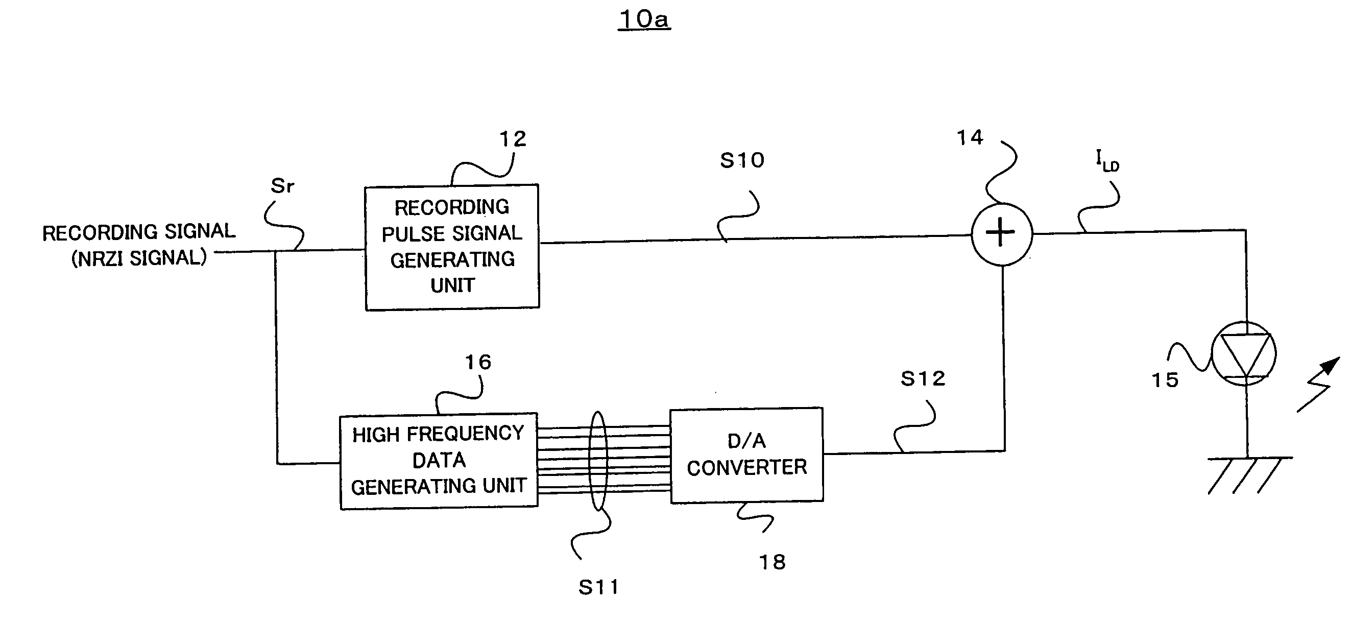
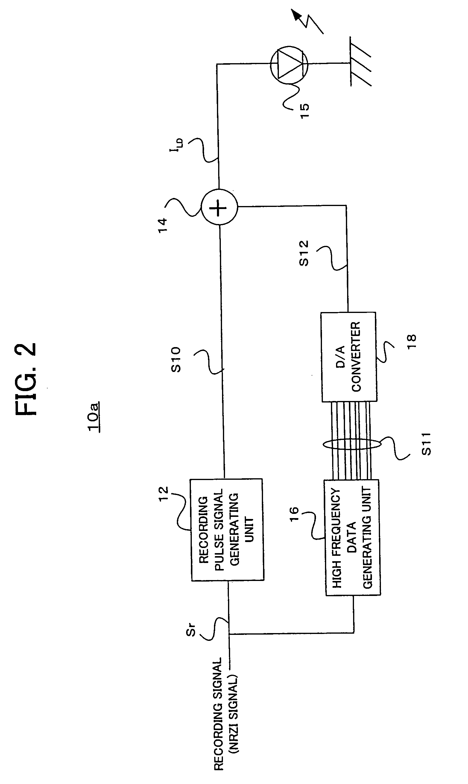
The present invention aims to reduce the effect of high frequency signals on recording quality in information recording apparatuses that use a high frequency signal superimposing method. The invention provides an information recording apparatus that includes a light source, a recording pulse generating unit, a high frequency signal generating unit, an adder, and a driving unit. The high frequency signal is generated as a digital signal and is added to the recording pulse signal to generate the driving pulse signal. This allows for control of the frequency and phase of the high frequency signal with high accuracy, and stable information recording. The amplitude of the high frequency signal is determined based on the recording mark length, and a high frequency signal table is used to refer to the frequency and amplitude of the high frequency signal corresponding to each recording mark. The recording pulse signal may be generated as an analog or digital signal, and the driving pulse signal is obtained by D / A converting the recording pulse signal and the high frequency signal. The technical effect of this invention is to improve the recording quality and stability of information recording.

Problems solved by technology

Hence, a noise characteristic of the semiconductor laser largely affects recording quality.
As a result, a noise occurs.
This kind of noise is particularly problematic in the field of the semiconductor laser.
As a result, there occurs a problem that the frequencies of the super imposed high frequency signal and the recording pulse signal become closer to each other, and interference occurs between them.
Specially, at the rise-up and fall-down portions of the recording pulse signal, an effect which the high frequency signal gives the recording pulse signal becomes large, and the recording quality may be deteriorated.
Thus, it is difficult to perform an optimum control of the frequency and an superimposing quantity of the high frequency signal according to a power of the laser light during recording the information, such as a write power, an erase power, and a bias power.
Also, since the high frequency signal is not synchronous with the recording pulse signal, the phase relation between the high frequency signal and the recording pulse signal cannot be controlled.
Therefore, a driving pulse signal for driving the semiconductor laser becomes unstable by the effect of the high frequency signal, and the recording quality of the information can be deteriorated.

Method used


Image

  • Information recording apparatus and information recording method
  • Information recording apparatus and information recording method
  • Information recording apparatus and information recording method

Examples


Embodiment Construction

[0029] The preferred embodiments of the present invention will now be described below with reference to the attached drawings.

[0030] [Principle]

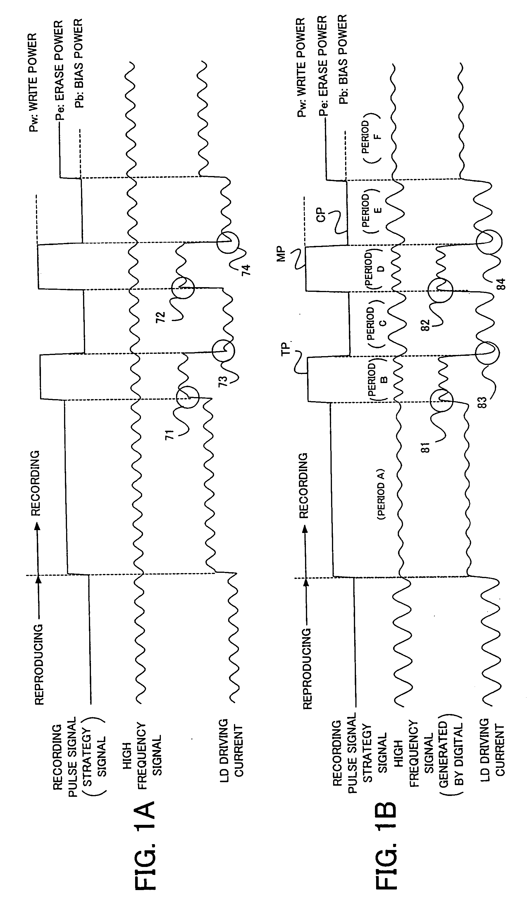
[0031]FIGS. 1A and 1B show examples of recording waveforms when the information recording is performed on the optical disc by the information recording apparatus. It is noted that the example is for a DVD-RW, which is an example of the optical disc. Since FIGS. 1A and 1B schematically show the relation between the signal waveforms, the frequency of each signal is different from its actual frequency.

[0032]FIG. 1A is an example when the high frequency signal generated by the analog circuit is superimposed on the recording pulse signal (strategy signal) in the high frequency signal superimposing method. In FIG. 1A, the recording pulse signal corresponds to the recording signal, and the signal includes three power levels, i.e., a write power Pw, an erase power Pe and a bias power Pb. The high frequency signal is superimposed on the recording p...


PUM

PropertyMeasurementUnit
recording poweraaaaaaaaaa
frequencyaaaaaaaaaa
constant angleaaaaaaaaaa

Abstract

An information recording apparatus irradiates a recording light, such as a laser light, on a recording medium, such as various kinds of optical discs, and records information. A recording pulse signal is generated based on a recording signal corresponding to the information to be recorded. The recording pulse signal is also called “strategy signal”, and the signal includes driving pulses which drive a light source for forming a recording mark on the recording medium. As to the recording light such as the laser light, the high frequency signal is superimposed for decreasing occurrence of noise due to mode hopping. The high frequency signal is generated as a digital signal, and the signal is added to the recording pulse signal to generate a driving pulse signal. Then, the light source is driven and the recording light is emitted. By generating the high frequency signal as the digital signal, it is possible to control a frequency and a phase thereof with high accuracy.

Description

BACKGROUND OF THE INVENTION [0001] 1. Field of the Invention [0002] The present invention relates to an information recording technique on an optical disc. [0003] 2. Description of Related Art [0004] Information recording on a recordable-type optical disc on which information is additionally recordable and rewritable is performed by driving a laser light source by a pulse signal corresponding to recording data, generating a recording laser light and irradiating it on an information recording surface of the optical disc. As a laser light source, a semiconductor laser such as a laser diode is utilized. Power of the recording laser light is controlled by controlling current quantity which is supplied to the laser diode by a driving circuit such as a laser driver. The laser driver switches plural current sources whose current quantity is preset according to a driving pulse signal corresponding to information to be recorded, and drives the laser diode. The driving pulse signal controls t...

Claims


Application Information

Patent Timeline
Patent Type & Authority Applications(United States)
IPC IPC(8): G11B7/00G11B7/0045G11B7/006G11B7/125G11B7/126
CPCG11B7/00456G11B7/126G11B7/0062
Inventor KATO, MASAHIROYONE, TATSUHIRO
Owner PIONEER CORP
Learn More