Radiographic apparatus and radiation detection signal processing method

a radiation detection and signal processing technology, applied in the field of radiographic equipment, can solve the problems of time delay of fpd and after-image problems, and achieve the effect of reducing time lags and high accuracy

Inactive Publication Date: 2005-02-10
SHIMADZU CORP
View PDF12 Cites 6 Cited by
  • Summary
  • Abstract
  • Description
  • Claims
  • Application Information

AI Technical Summary

Benefits of technology

This invention has been made having regard to the state of the art noted above, and its object is to provide a radiographic apparatus and a radiation detection signal processing method for fully eliminating time lags, due to a radiation detecting device, of radiation detection signals taken from the radiation detecting device, thereby obtaining a subtraction image with high accuracy.
With the radiographic apparatus according to this invention, radiation detection signals are outputted from the radiation detecting device at predetermined sampling time intervals as radiation is emitted from the radiation emitting device to an object under examination. A live image and a mask image are obtained from these radiation detection signals, and are subjected to a subtraction process to obtain a subtraction image. A lag-behind part included in each of the radiation detection signals taken at the sampling time intervals is regarded as due to an impulse response formed of one exponential function or a plurality of exponential functions with different attenuation time constants. Such lag-behind parts are removed from the radiation detection signals by a recursive computation to obtain corrected radiation detection signals. In order to pick up a live image and a mask image continually, radiation detection signals for the live image and radiation detection signals for the mask image are continually detected at the sampling time intervals. Thus, the lag-behind parts of these signals are linked in time. When an image accompanying the lag-behind parts is picked up and thereafter a different image is picked up, the lag-behind parts influence the latter image also. Such lag-behind parts influencing one another are used to eliminate fully the time delays of the radiation detection signals due to the radiation detecting device. The live image and mask image are obtained from the corrected detection signals having the mutually influencing lag-behind parts removed. Consequently, the lag-behind parts are fully removed from the subtraction image obtained by performing the subtraction process on the live image and mask image.
This radiation detection signal processing method allows the radiographic apparatus according to the invention to be implemented in an advantageous manner.

Problems solved by technology

However, where a flat panel X-ray detector (hereinafter called “FPD” as appropriate) having numerous X-ray detecting elements arranged longitudinally and transversely on an X-ray detecting surface is used as a radiation detector (radiation detecting device) for detecting such images, time delays of the FPD could cause after-images.
Thus, a problem of after-images arises unless lag-behind parts are fully eliminated.

Method used


Image

  • Radiographic apparatus and radiation detection signal processing method
  • Radiographic apparatus and radiation detection signal processing method
  • Radiographic apparatus and radiation detection signal processing method

Examples


Embodiment Construction

Preferred embodiments of this invention will be described in detail hereinafter with reference to the drawings.

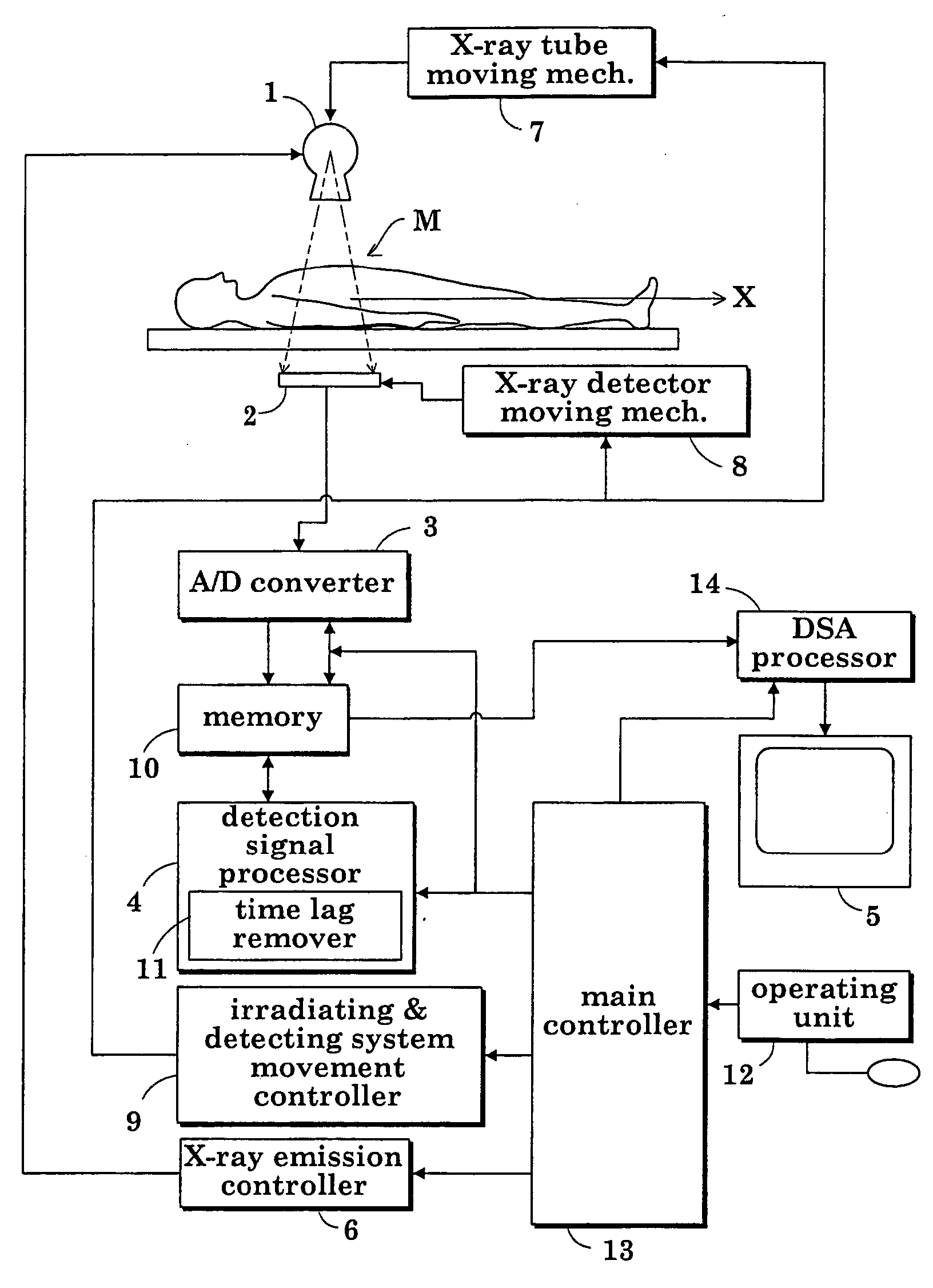
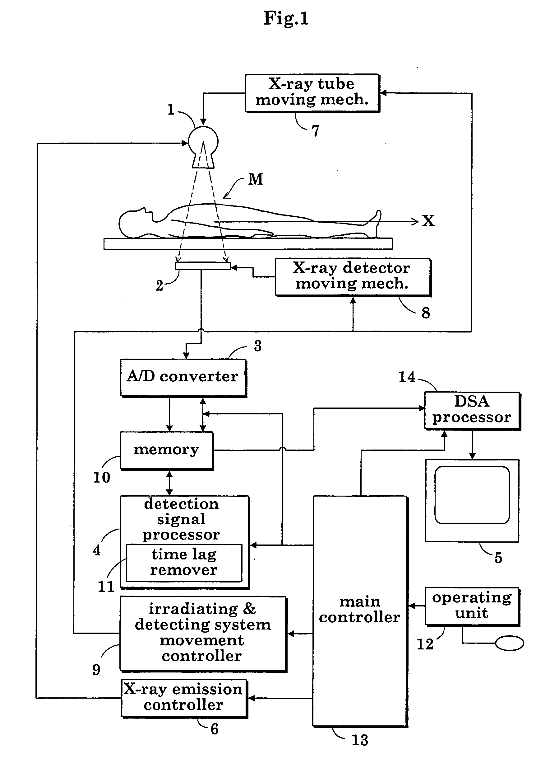
FIG. 1 is a block diagram showing an overall construction of a fluoroscopic apparatus according to this invention.

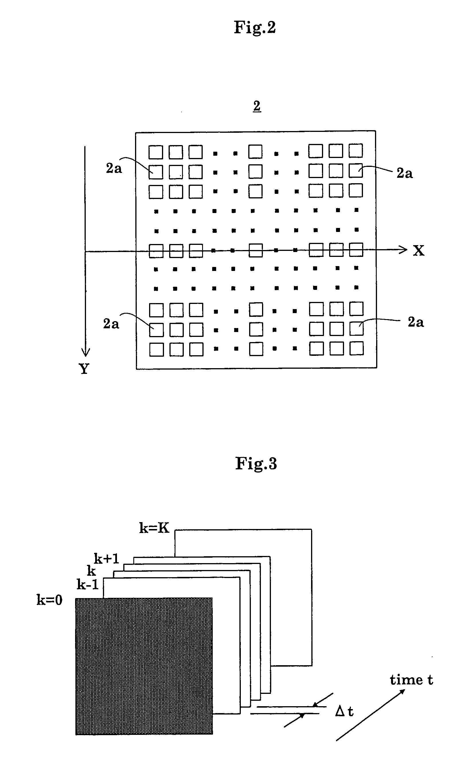
As shown in FIG. 1, the fluoroscopic apparatus includes an X-ray tube (radiation emitting device) 1 for emitting X rays toward a patient M, an FPD 2 (radiation detecting device) for detecting X rays transmitted through the patient M, an analog-to-digital converter 3 (signal sampling device) for digitizing X-ray detection signals (radiation detection signals) taken from the FPD (flat panel X-ray detector) 2 at predetermined sampling time intervals Δt, a detection signal processor 4 for creating X-ray images based on X-ray detection signals outputted from the analog-to-digital converter 3, and an image monitor 5 for displaying the X-ray images created by the detection signal processor 4. That is, the apparatus is constructed to acquire X-ray images from the X-...


PUM


Abstract

A subtraction image is obtained, by a subtraction process (DSA process), from a live image and a mask image. A lag-behind part included in each X-ray detection signal is considered due to an impulse response formed of exponential functions. The lag-behind part is removed from each X-ray detection signal by a recursive computation to obtain a corrected X-ray detection signal. The live image and mask image are obtained from such corrected detection signals.

Description

BACKGROUND OF THE INVENTION (1) Field of the Invention This invention relates to a radiographic apparatus for medical or industrial use and a radiation detection signal processing method, for obtaining radiographic images based on radiation detection signals fetched at predetermined sampling time intervals by a signal sampling device from a radiation detecting device as radiation is emitted from a radiation emitting device. More particularly, the invention relates to a technique for improving an image quality vulnerable to impairment of DSA (subtraction process) images due to time lags occurring with the radiation detecting device. (2) Description of the Related Art Conventionally, a type of radiographic apparatus is designed for use in digital subtraction angiography (DSA) to observe the conditions of blood vessels of a patient. This apparatus is operable to perform X-ray radiography of a predetermined site of the patient before injection of a contrast medium, and then radiogra...

Claims


Application Information

Patent Timeline
Patent Type & Authority Applications(United States)
IPC IPC(8): G01T1/00A61B6/00G06T1/00G06T5/20G06T5/50H04N5/325H05G1/00
CPCA61B6/481H04N5/325A61B6/504A61B6/487A61B6/00
Inventor OKAMURA, SHOICHIFUJII, KEIICHIADACHI, SUSUMUHIRASAWA, SHINYAYOSHIMUTA, TOSHINORITANABE, KOICHIASAI, SHIGEYANISHIMURA, AKIHIRO
Owner SHIMADZU CORP
Why Eureka
Try Eureka