Arrangement structure of machine tool

a technology of arrangement structure and machine tool, which is applied in the field of arrangement structure of machine tools, can solve the problems of increasing the support stiffness of the column, x axis, and the arrangement of the column on the bed, and achieves the effect of improving the maintenanceability of the column

Inactive Publication Date: 2005-02-10
DMG MORI SEIKI CO LTD
View PDF8 Cites 21 Cited by
  • Summary
  • Abstract
  • Description
  • Claims
  • Application Information

AI Technical Summary

Benefits of technology

[0023] In the embodiment, since the maintenance opening is formed in the column to face the spindle opening of the saddle which allows movement of the rear end portion of the spindle in the Y axis direction, inspection and maintenance of the spindle from the backside thereof can be easily and surely performed, so that the maintainability thereof can be improved.

Problems solved by technology

In the meantime, the structure in which the column is arranged on the bed to be movable in the X axis direction has a disadvantage in an aspect to increase support stiffness for the column.
When such a column fixing structure is adopted, and when it is attempted to adopt the conventional arrangement structure in which electrical wires and pipes are arranged on the backside of the column as described above, there arises a need to form, in the fixedly arranged column, an opening which corresponds to movable ranges of the above-described bracket and movable side relay box, so that there is a possibility to impair the advantage of increasing the support stiffness for the column as a result.

Method used


Image

  • Arrangement structure of machine tool
  • Arrangement structure of machine tool
  • Arrangement structure of machine tool

Examples


Embodiment Construction

[0031] Hereinafter, an embodiment of the present invention will be described based on the attached drawings.

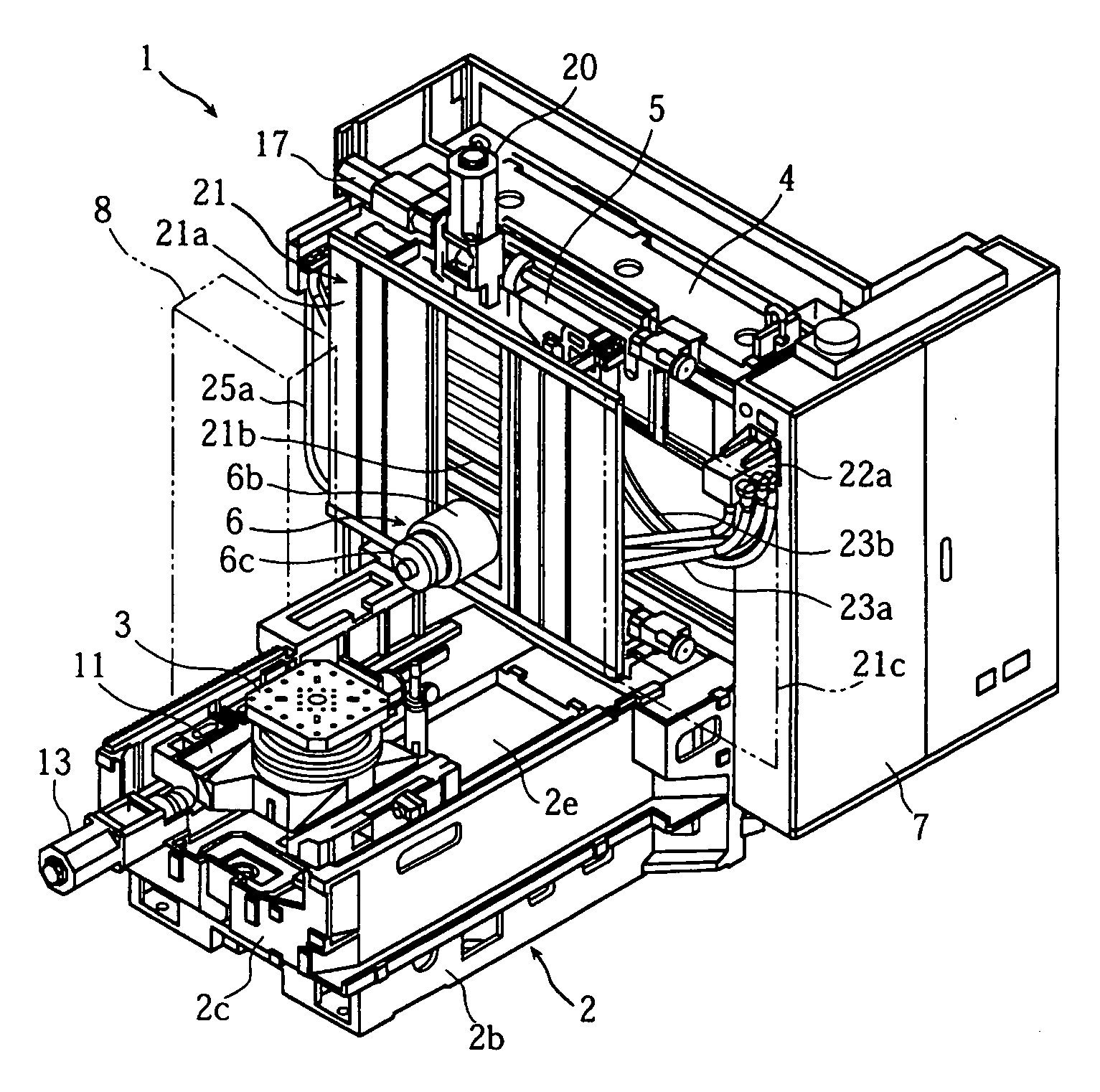
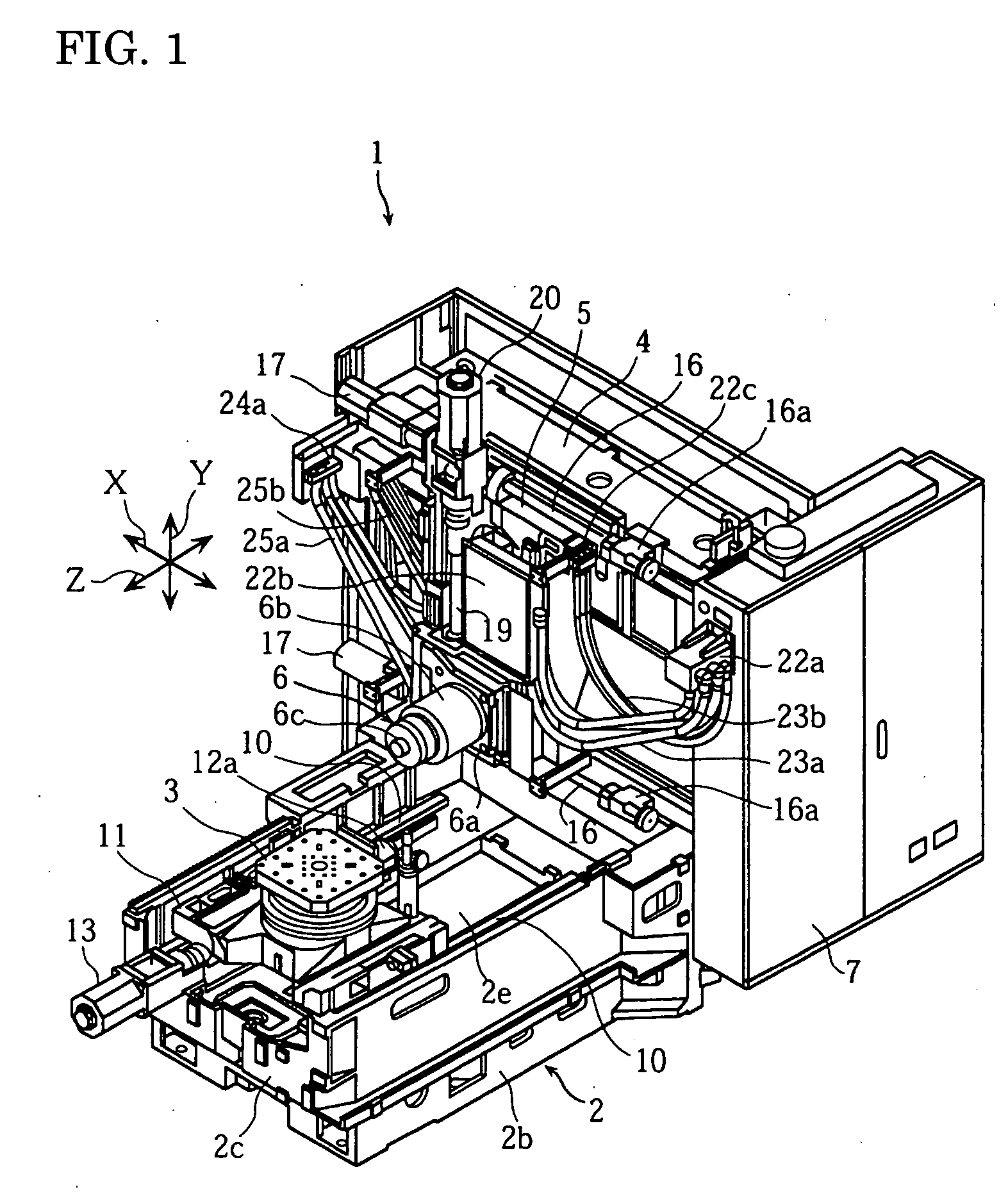
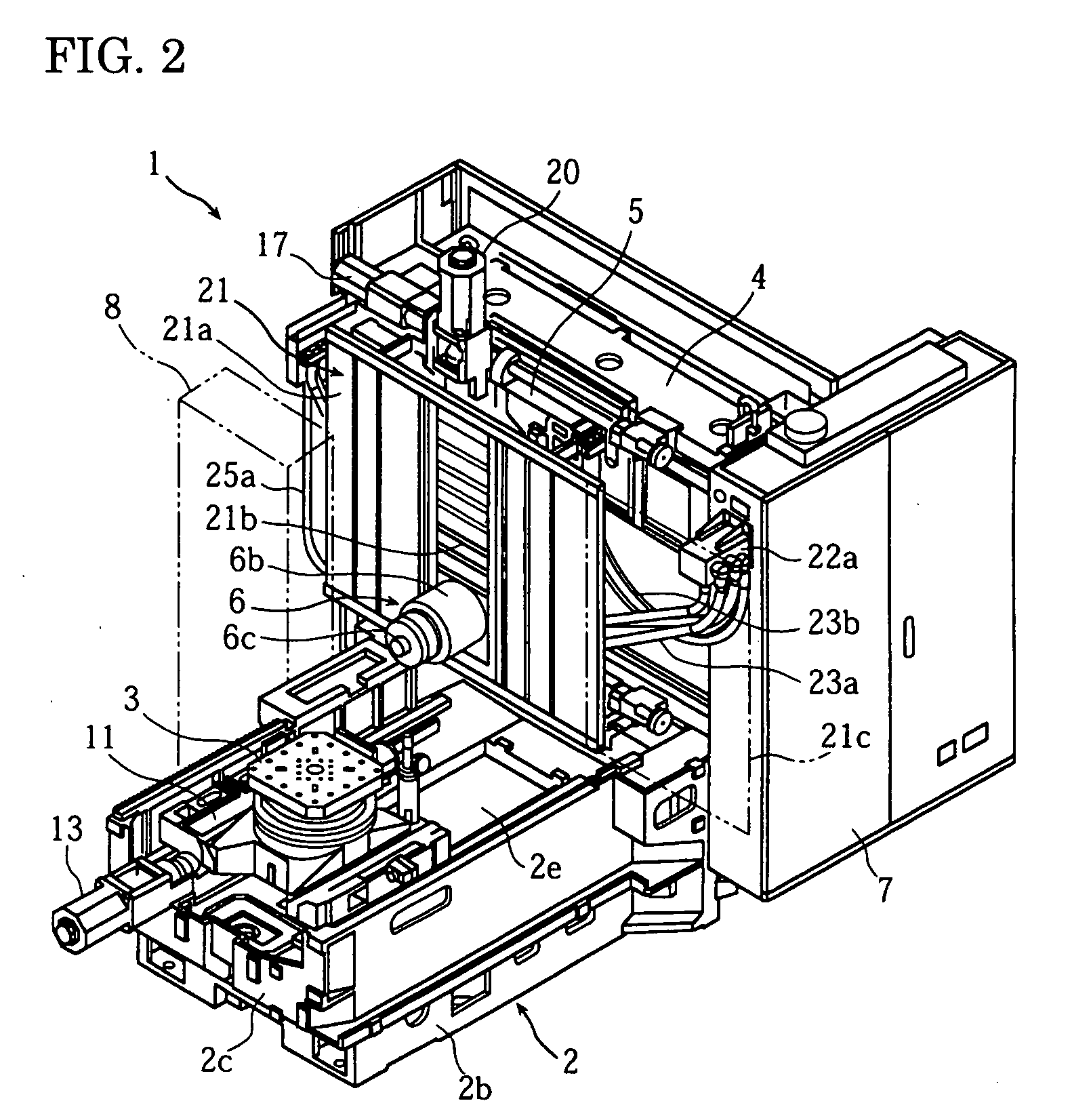
[0032]FIG. 1 to FIG. 6 are views for describing an arrangement structure of a horizontal machining center according to one embodiment of the present invention, FIG. 1 and FIG. 2 are perspective front views of the horizontal machining center, FIG. 3 is a perspective front view showing the arrangement structure, FIG. 4 and FIG. 5 are a right side view and a cross-sectional left side view of the horizontal machining center respectively, and FIG. 6 is a perspective view of a bed and a column seen from a bottom surface. Incidentally, in this specification, front / rear and left / right mean front / rear and left / right seen from the front of the machine.

[0033] In the figures, a numeral 1 denotes a horizontal machining center. This horizontal machining center 1 has a schematic structure as follows. A bed 2 has a substantially rectangular frame shape in a plan view. On an upper surface of...


PUM

PropertyMeasurementUnit
arrangement structureaaaaaaaaaa
flexibilityaaaaaaaaaa
stiffnessaaaaaaaaaa

Abstract

The present invention provides an arrangement structure of a machine tool which is capable of compactly arranging electrical wires and pipes for coolant and the like without impairing support stiffness for a column, and simplifying the arrangement structure, while adopting a column fixing structure. In the present invention, an arrangement structure of a machine tool 1 includes a bed 2, a table 3 arranged on the bed 2 to be movable in a forward and backward (Z axis) direction, a column 4 fixed upright on the bed 2, a saddle 5 arranged on a front surface of the column 4 to be movable in a left and right (X axis) direction, a spindle head 6 arranged on a front surface of the saddle 5 to be movable in an up and down (Y axis) direction, a spindle 6c supported by the spindle head 6 to horizontally face a front side of the machine, a wire supply portion arranged on the column 4 side, and flexible tubes 23a for spindle side electrical wires having flexibility and arranged on a front side of the column 4, the flexible tubes 23a for the spindle side electrical wires connecting the wire supply portion and the spindle head 6.

Description

BACKGROUND OF THE INVENTION [0001] 1. Filed of the Invention [0002] The present invention relates to a machine tool such as a horizontal machining center in which a spindle is supported horizontally by a column which is fixed upright on a bed, and particularly relates to an arrangement structure of electrical wires, pipes of coolant and the like thereof. [0003] 2. Discussion of the Related Art [0004] In a machine tool such as the above-mentioned horizontal machining center, it is necessary to connect a fixed side including a bed, a column, and so on and a movable side including a spindle head, a saddle and so on by electrical wires such as power lines of an electrical motor, various signal lines and the like, and various pipes such as supply pipes of coolant, compressed air and the like, oil supply and drain pipes of spindle cooling oil and the like. [0005] Conventionally, as an arrangement structure of such electrical wires and pipes in a horizontal machining center in which a tabl...

Claims


Application Information

Patent Timeline
Patent Type & Authority Applications(United States)
IPC IPC(8): B23C1/027B23Q1/00B23Q1/01
CPCB23Q1/0009B23Q1/015Y10T408/92Y10T409/309576Y10T409/30392Y10T409/30952
Inventor HIRAMOTO, KAZUYUKIMORIGUCHI, KAZUTOYOYASUMATSUYA, KAORU
Owner DMG MORI SEIKI CO LTD
Why Eureka
Try Eureka