
High-voltage equipment housing and high-voltage connector

a technology of high-voltage equipment and connectors, which is applied in the direction of electrical devices, battery/fuel cell control arrangements, coupling device connections, etc., to achieve the effect of ensuring the safety of the operator

Active Publication Date: 2005-02-10
TOYOTA JIDOSHA KK
View PDF6 Cites 48 Cited by
  • Summary
  • Abstract
  • Description
  • Claims
  • Application Information

AI Technical Summary

Benefits of technology

[0008] It is an object of the present invention to provide a high-voltage equipment housing sufficiently ensuring safety of an operator who works on high-voltage equipment.
[0009] It is another object of the present invention to provide a high-voltage equipment housing sufficiently ensuring safety of an operator in conducting maintenance of high-voltage equipment.
[0010] It is still another object of the present invention to provide a high-voltage connector sufficiently ensuring safety of an operator who works on high-voltage equipment.
[0011] It is a further object of the present invention to provide a high-voltage connector sufficiently ensuring safety of an operator in conducting maintenance of high-voltage equipment.
[0013] A high-voltage connector, for example, serving as the connection unit is provided to the high-voltage equipment housing. The connection unit makes an electrical connection between the external equipment located outside the high-voltage equipment housing and the high-voltage equipment. As the connection unit is attached by the attaching unit, the mechanical connection of the connection unit is not released by the connection unit only. In response to detachment of the attaching unit, the changing unit changes the state of the electrical connection between the high-voltage equipment and the external equipment by means of the connection unit to the disconnected state. Thus, when an operator is going to detach the high-voltage connector or the connection unit, the operator detaches, before releasing the mechanical connection by withdrawing the high-voltage connector, the attaching unit which prevents a situation that only the mechanical connection is released. The detachment of the attaching unit causes the changing unit to change the state of the electrical connection to the disconnected state thereby change a state where a high voltage is supplied or a high voltage can be supplied to a state where a high voltage cannot be supplied. Accordingly, the high-voltage equipment housing sufficiently ensuring safety of an operator working on high-voltage equipment can be provided.
[0025] The connection unit of the high-voltage equipment housing is placed at a position touchable by a hand of a person. Then, when an operator is going to detach the high-voltage connector or the connection unit with the hand, the operator detaches, before releasing the mechanical connection by withdrawing the high-voltage connector, the attaching unit which prevents a situation that only the mechanical connection is released. The state is accordingly changed to a state where a high voltage cannot be supplied. Accordingly, the high-voltage equipment housing sufficiently ensuring safety of an operator working on high-voltage equipment can be provided.

Problems solved by technology

The disclosed vehicle structure described above, however, has the following problem.

Method used


Image

  • High-voltage equipment housing and high-voltage connector
  • High-voltage equipment housing and high-voltage connector
  • High-voltage equipment housing and high-voltage connector

Examples


first embodiment

[0038] First Embodiment

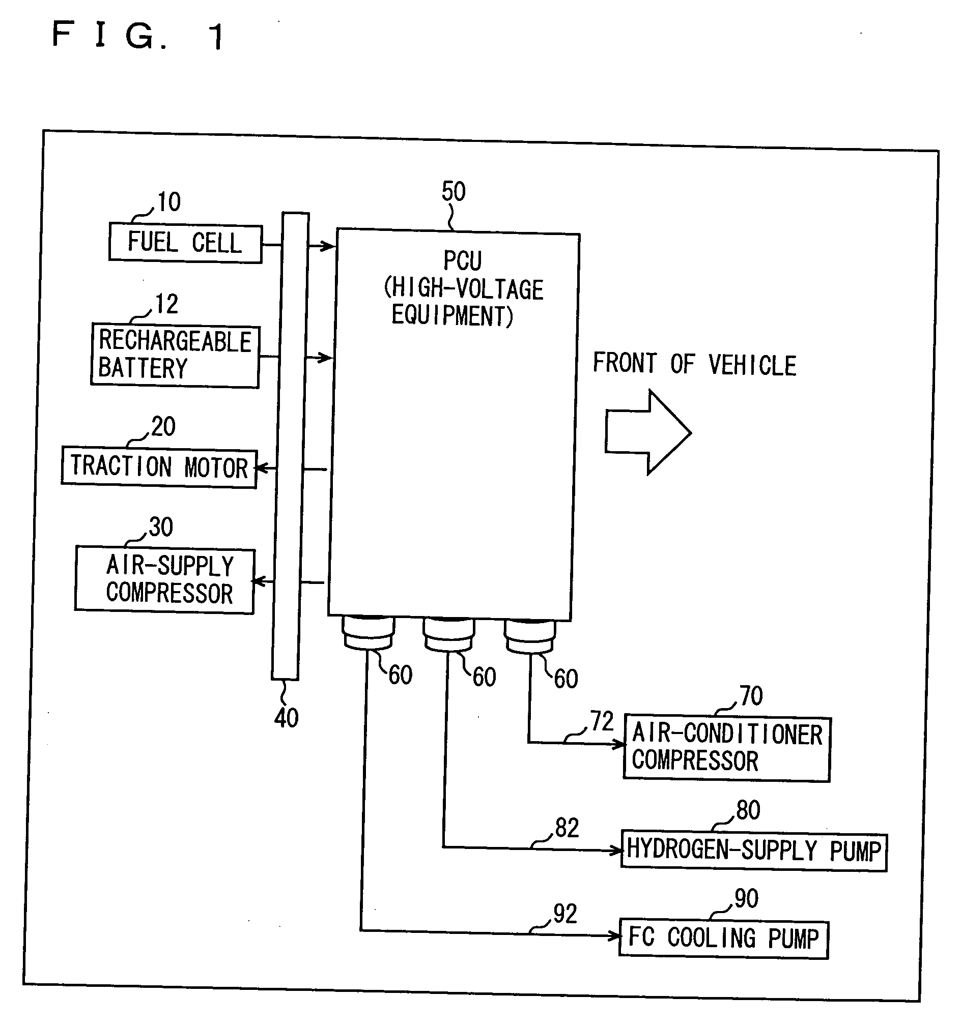
[0039] Referring to FIG. 1, a vehicle is described that is a vehicle on which a high-voltage equipment housing (hereinafter referred to as PCU box) is mounted according to this embodiment and which drives an electric motor by a fuel cell and a rechargeable battery. The block diagram of FIG. 1 is a schematic diagram of the vehicle as seen from the above. The vehicle includes a fuel cell (FC) 10 generating electricity by a reaction of hydrogen supplied from a hydrogen-storing alloy or hydrogen supplied through reformation of methanol or the like into hydrogen and oxygen contained in the air, a traction motor 20 for running the vehicle, a rechargeable battery 12 which is charged with electricity generated by traction motor 20 functioning as a generator in a regenerative breaking operation and which discharges electricity in an accelerating operation so as to compensate for a shortage of electricity that cannot be covered by an output from fuel cell 10, and an air...

second embodiment

[0069] Second Embodiment

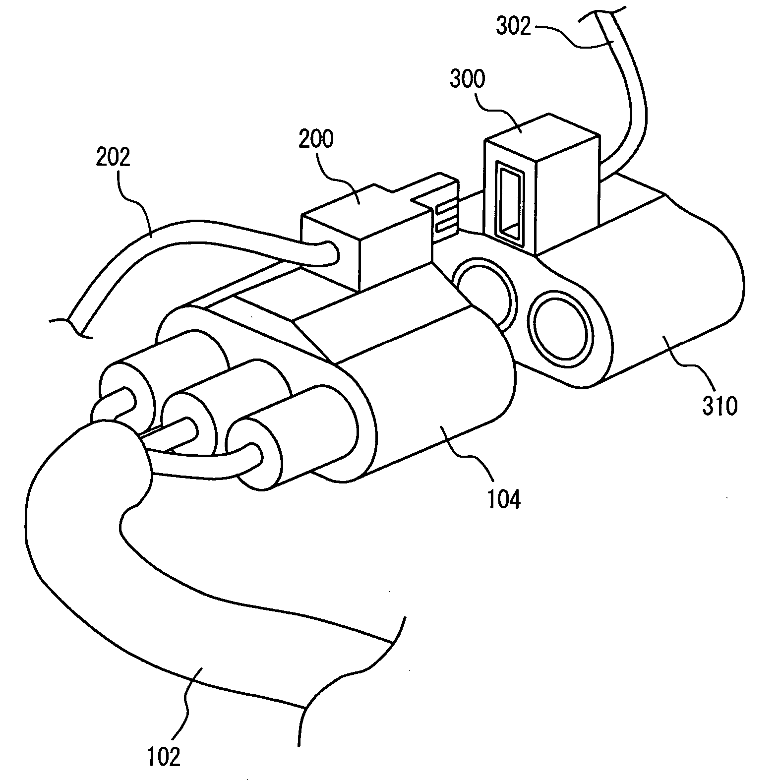
[0070] Referring to FIG. 8, a high-voltage connector is described according to this embodiment. To the high-voltage connector of this embodiment, the interlock signal line described in connection with the first embodiment is connected. Here, a structure and a flowchart are the same as those of the first embodiment except for the above characteristic and thus detailed description thereof is not repeated here.

[0071] With reference to FIG. 8, the high-voltage connector according to this embodiment includes a connector 104, a connector joint 310 fit on connector 104, an interlock male unit 200 provided on connector 104, and an interlock female unit 300 provided on connector joint 310.

[0072] An interlock signal line 202 is connected to interlock male unit 200 and an interlock signal line 302 is connected to interlock female unit 300. FIG. 8 shows that connector 104 and connector joint 310 are in a disconnected state.

[0073] When connector 104 and connector joint...


PUM


Abstract

A PCU having an inverter and the like includes a connector electrically connecting the PCU and external equipment located outside the PCU, a safety bar attaching the connector for preventing the connector from being touched, and an ECU detecting that an interlock circuit is opened via an interlock signal line in response to detachment of the safety bar to shut off supply of electric power to the PCU.

Description

BACKGROUND OF THE INVENTION [0001] 1. Field of the Invention [0002] The present invention relates to a structure of high-voltage equipment as well as a high-voltage connector for safely conducting maintenance and inspection of the high-voltage equipment mounted on an electric vehicle. In particular, the present invention relates to a structure of high-voltage equipment and a high-voltage connector with which a high-voltage power supply can mechanically and electrically be shut off to allow maintenance and inspection to be conducted. [0003] 2. Description of the Background Art [0004] A conventional electric vehicle is structured by placing a circuit-breaker unit and high-voltage equipment in a space isolated from a passenger compartment and a trunk and covering the space with a maintenance lid to hold the circuit-breaker unit and the high-voltage equipment within the closed space. For maintenance and inspection of the high-voltage equipment, sufficient safety measures for ensuring sa...

Claims


Application Information

Patent Timeline
Patent Type & Authority Applications(United States)
IPC IPC(8): B60R16/02H01R13/46H01R13/518H01R13/641H01R13/713H01R13/73H02G3/16
CPCB60L3/0069B60L3/04B60L11/123B60L11/1887H01R13/518Y02T90/34H01R13/713H01R2201/26Y02T10/6217Y02T10/7077H01R13/641B60L1/003B60L2240/34B60L50/61B60L58/40Y02T10/62Y02T10/70Y02T10/7072Y02T90/40
Inventor FURUTA, NORIFUMIINAGAKI, MASAMIKANEKO, MASAAKIKAWAI, TATSUYA
Owner TOYOTA JIDOSHA KK
Features
  • Generate Ideas
  • Intellectual Property
  • Life Sciences
  • Materials
  • Tech Scout
  • Unparalleled Data Quality
  • Higher Quality Content
  • 60% Fewer Hallucinations
Learn More