Implant for the dynamic fixation of a corrective osteotomy

a dynamic fixation and osteotomy technology, applied in the field of implants for corrective osteotomy, can solve the problems of difficult insertion of braces, inability to completely rotate stable fixation of bone fragments, and stress on the foot, so as to improve the healing progress, simplify the handling, and enhance the growth of bone formation

Inactive Publication Date: 2005-02-10
KUPA PRAZISIONSMASCH
View PDF14 Cites 19 Cited by
  • Summary
  • Abstract
  • Description
  • Claims
  • Application Information

AI Technical Summary

Benefits of technology

[0008] By this configuration, it is particularly easy to introduce the implant by its shaft into the marrow space of a bone, whereby the anchoring edges will bear against the inner side of the bone and allow for a rotationally fast fixation of the implant. This configuration also enables the bone fragments to be sufficiently displaced and precisely positioned.
[0009] When using the implant according to the invention for the dynamic fixation of a corrective osteotomy, the provision of the crank between the fixing section and the anchoring section, in particular, enables a greater dislocation or shift between separated bone parts or fragments such that larger corrections will be feasible by a single cut, for which hitherto several cuts have, for instance, been required. Furthermore, the use of the implant according to the invention, in addition to enabling a greater dislocation as a function of the size of the crank, and hence an improved correction, also directly provides for an accordingly enhanced rotability of the joint surface by applying the cut remotely to the base so as to enable, again by a single cut, both a dislocation by a greater extent than in the prior art and a rotation of the joint surface, to which end two cuts involving accordingly elevated operative expenditures have usually been required according to the prior art known so far.
[0010] By using the implant according to the invention, which comprises an anchoring shaft rigid in the longitudinal direction and is preferably provided with anchoring edges for fixation to the inner side of a long bone, even the operative procedure can be shortened and simplified by minimal invasive surgery, since the expansion of the cut will, for instance, be effected by the insertion or introduction of the anchoring shaft between the bone fragments after the application of a shortened cut length in the region of the bone to be separated and after the separation or cutting of the same, whereupon the anchoring shaft is immediately inserted or driven into the long bone after the expansion of the cut and will be immediately firmly anchored within the long bone via the preferably provided anchoring edges such that no additional cumbersome steps will be required for the fixation of the implant, apart from the simple fixation via the spongiosa screw in the region of the fixing section.
[0016] For a particularly simple fixation of the fixing section, the implant according to the invention is preferably designed in a manner that the hole of the fixing section is designed as a cylindrical bore which, together with the head-near, cylindrical end of the spongiosa screw, forms an angularly stable connection between the spongiosa screw and the implant.
[0017] In order to enhance bone formation growth after the insertion of the implant, and hence improve the healing progress, and to enable simplified handling during its introduction into the interior of the long bone, it is proposed according to a further preferred embodiment that the crank is designed to include a diminution or reduction in its lateral regions. By providing such a diminution or reduction, the implant may also be readily removed after a period of, for instance, three to four months, whereby sufficient bone formation to ensure consolidation between the individual bone parts or fragments will be safeguarded particularly in the region of reduction.
[0018] For a particularly simple manufacture, it is proposed according to a further preferred embodiment that it is made in one piece of metal. Such metals or metal alloys well tested for use as implants for quite some time are known. Particularly where no removal of the implant is to be effected in order to increase the stability of the connection between the separated bone parts, it is proposed according to a further preferred embodiment of the invention that it is made of resorbable plastics.

Problems solved by technology

That brace does not allow for a completely rotationally stable fixation of the bone fragments to be connected.
This involves disadvantages, inter alia, with the foot stressed under load.
Furthermore, the insertion of the brace is difficult, because the bone fragment to be displaced will be under chordal tension in most cases.
Breakage of the brace may, moreover, occur during explantation.

Method used


Image

  • Implant for the dynamic fixation of a corrective osteotomy
  • Implant for the dynamic fixation of a corrective osteotomy
  • Implant for the dynamic fixation of a corrective osteotomy

Examples


Embodiment Construction

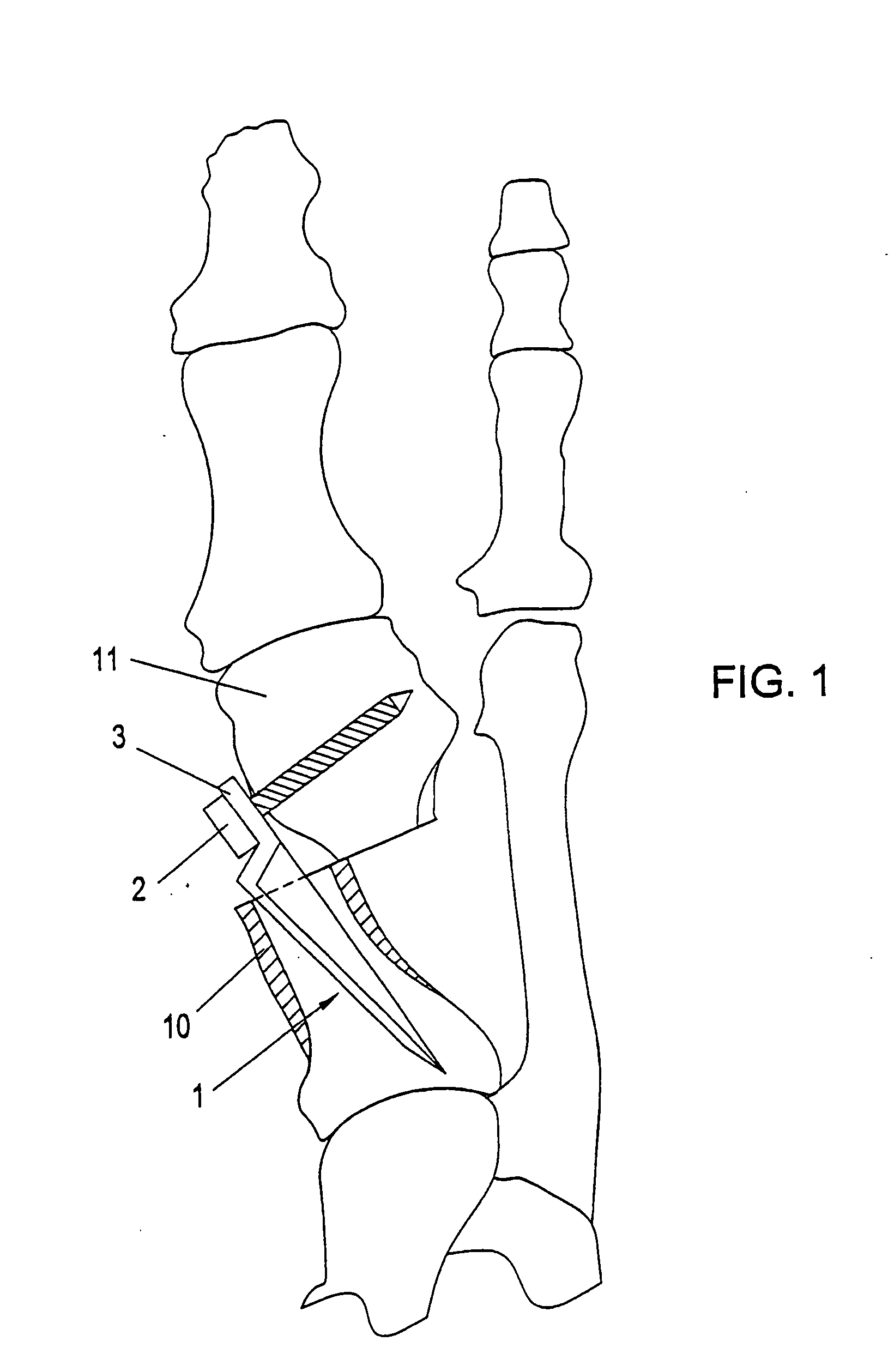
[0025] A way of surgically correcting halux valgus consists in separating the malaligned metatarsal I and fixing same in the corrected position. In FIG. 1, such a fixation by the aid of the implant according to FIG. 2 is illustrated. After having separated the bone, the anchoring shaft 1 with the sharpened drive-in end is driven into the marrow space of the bone fragment 10 until the crank comes to lie on the level of the osteotomy. After this, the second bone fragment 11 is fixed to the fixing section 3 by the aid of a spongiosa screw 1. The implant enables a corrective osteotomy that is stable in the frontal and transverse planes as well as in terms of rotation and which allows for the dynamic compression of the bone fragments in the axial direction. The implant stands out for its high static stability. Fracture during explantation need not be feared.

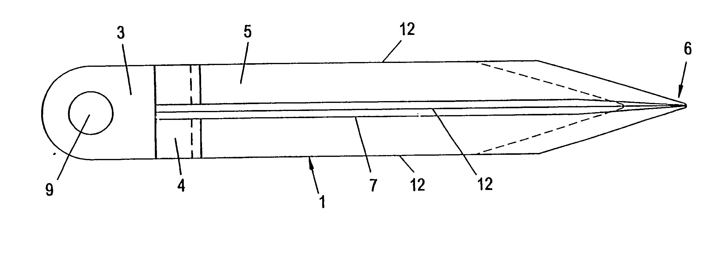
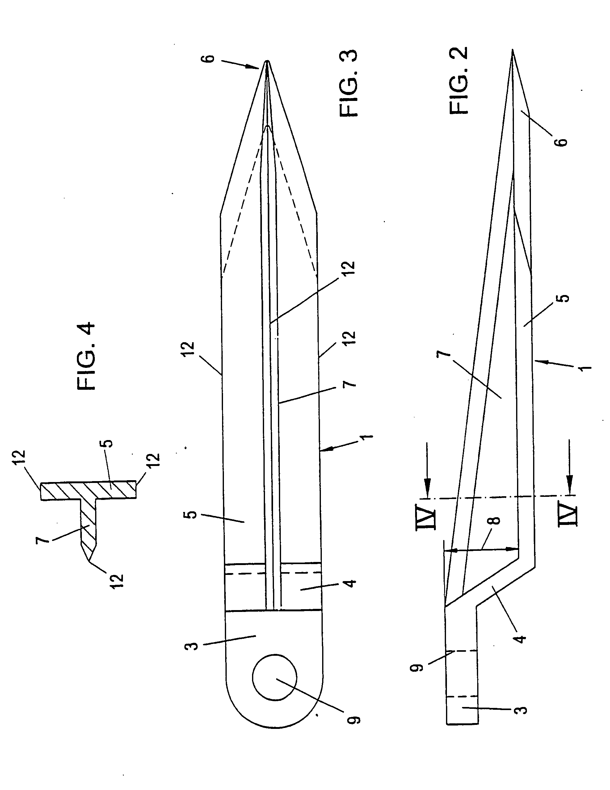
[0026]FIG. 2 illustrates an embodiment of the implant from the side. The implant is comprised of an anchoring shaft 1, which is con...


PUM


Abstract

In an implant for the dynamic fixation of a corrective osteotomy, it is provided that a fixing section (3) including a hole (9) for the reception of a spongiosa screw is connected via a crank (4) with a particularly laterally offset, elongated anchoring section (1) designed in the longitudinal direction as a rigid anchoring shaft (1), which is preferably configured to include at least three external anchoring edges (12) capable of engaging the inner side of a long bone, thus providing an implant with an improved fixation and a larger corrective range.

Description

[0001] The present application is a continuation application of PCT / AT03 / 00067, filed on Mar. 11, 2003. FIELD OF THE INVENTION [0002] The present invention relates to an implant for the dynamic fixation of a corrective osteotomy, wherein a fixing section including a hole for the reception of a spongiosa screw is connected via a crank with a particularly laterally offset, elongated anchoring section designed in the longitudinal direction as a rigid anchoring shaft. [0003] An exemplary, special field of application of such implants comprises corrective osteotomy for the treatment of axial malalignments on metatarsal bones in man, such as, for instance, halux valgus. DESCRIPTION OF THE PRIOR ART [0004] From WO 97 / 35528, an implant designed as a V-shaped brace is known for the treatment of an axial malalignment of a metatarsal bone. That brace does not allow for a completely rotationally stable fixation of the bone fragments to be connected. This involves disadvantages, inter alia, with...

Claims


Application Information

Patent Timeline
Patent Type & Authority Applications(United States)
IPC IPC(8): A61B17/68A61B17/72A61B17/80
CPCA61B2017/565A61B17/68A61B17/72A61B17/8095A61B17/7291A61B17/80A61B17/809A61B17/7233
Inventor FRANK, ERICH
Owner KUPA PRAZISIONSMASCH
Why Eureka
Try Eureka