Arterial hole closure apparatus

US20050033359A1Inactive Publication Date: 2005-02-10COVIDIEN AG

Image

  • Arterial hole closure apparatus
  • Arterial hole closure apparatus
  • Arterial hole closure apparatus

Examples


Embodiment Construction

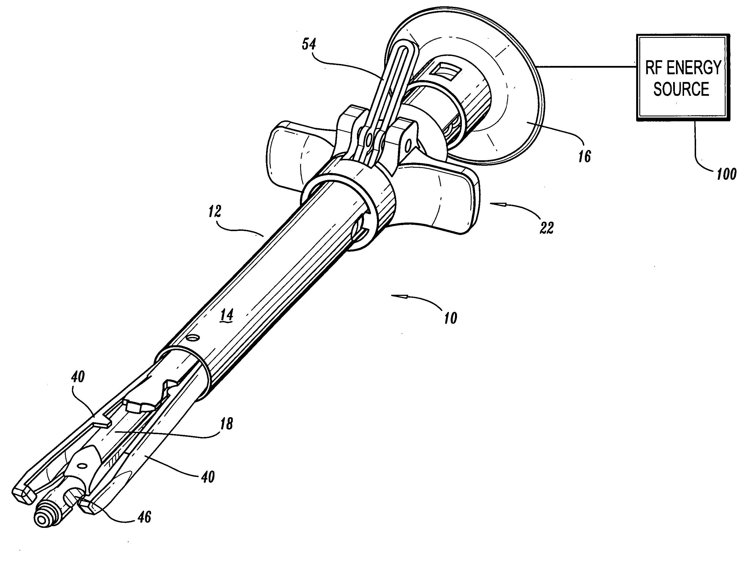
[0025] In general, the object of the apparatus is to close an access opening in a tissue wall following a surgical procedure (e.g., a coronary catheterization procedure, bowel closure, gall bladder closure, port side closure, hernia closure, vein closure, trauma induced openings and defects) to stem the flow of blood or other biological liquid through the opening while permitting post operative flow through the tissue conduit. In the drawings and in the description which follows, the term “proximal”, as is traditional, will refer to that end of the apparatus, or component thereof, which is closer to the operator, while the term “distal” will refer to that end of the apparatus, or component thereof, which is more remote from the operator.

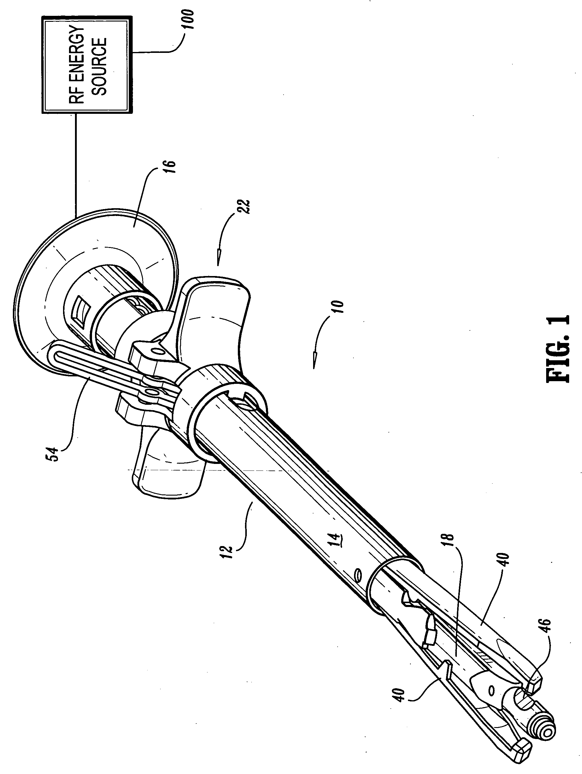
[0026] Referring now in detail wherein like reference numerals identify similar components throughout the several views, FIG. 1 illustrates in perspective the apparatus in accordance with the principles of the present disclosure. Although the presen...


PUM


Abstract

A closure device for use following various surgical procedures to close access openings through the tissue wall while permitting post operative flow through the tissue conduit includes a housing having proximal and distal ends, and defining a longitudinal axis, first and second tissue everting members mounted adjacent the distal end of the housing and first and second jaw members mounted adjacent the first and second tissue engaging members. The first and second arterial tissue everting members are dimensioned for at least partial positioning within the access opening in the tissue wall and are deployable in at least a radial outward direction relative to the longitudinal axis of the housing to engage respective opposed tissue portions on opposed sides of the opening and move the tissue portions to an everted condition thereof. The first and second jaw members are adapted for relative movement between an open position to facilitate positioning about the tissue portions in the everted condition and a closed position to at least partially draw the tissue portions together to an at least partial approximated condition. Electrodes are associated with the first and second jaw members and arranged to contact the respective tissue portions. The electrodes are adapted to be connected to a radiofrequency energy source whereby energy is transmitted through the electrode to seal the tissue positions between the first and second jaw members to substantially close the opening.

Description

CROSS REFERENCE TO RELATED APPLICATIONS [0001] This application is a continuation-in-part of U.S. application Ser. No. 09 / 883427 filed on Jun. 18, 2001 by Pedros et al. which is a continuation of U.S. application Ser. No. 09 / 503510 filed on Jun. 14, 2000 by Roberto Pedros the entire contents of both of which are hereby incorporated by reference herein.BACKGROUND [0002] 1. Technical Field [0003] The present disclosure relates to a closure device used for closing an access opening formed through a tissue conduit wall while permitting post operative blood flow through the tissue conduit. [0004] 2. Background of the Related Art [0005] Certain surgical procedures require the surgeon to puncture the walls of tissue conduits for the introduction of dilators, catheters and the like. For example, when performing a catheterization procedure, e.g., an angiography or angioplasty, a sharpened hollow needle is first percutaneously introduced into the vascular system. A guide wire is then inserted...

Claims


Application Information

Patent Timeline
10 Feb 2005
Publication
US20050033359A1
IPC
A61B17/10; A61B17/00; A61B17/04; A61B18/12; A61B18/14
CPC
A61B17/0057; A61B18/1402; A61B18/1442; A61B2018/0063; A61B2018/00404; A61B2018/00619; A61B2017/00504
Inventors
DYCUS, SEAN T.