Structural/biological implant system

a bio-injection and implant technology, applied in the field of bio-injection systems, can solve the problems of inadequate bone height and/or width for the placement of standard endosseous dental implants, bone resorption after tooth loss, and insufficient bone volume, etc., to achieve the effect of increasing bone height and volume in the patien

Inactive Publication Date: 2005-02-10
UNIV OF CONNECTICUT
View PDF22 Cites 39 Cited by
  • Summary
  • Abstract
  • Description
  • Claims
  • Application Information

AI Technical Summary

Benefits of technology

[0009] Generally, a portion of the implant is fastened into existing bone, with the remainder of the implant extending outside of existing bone. The extending or exposed portion of the implant has an osteointegrative surface which may include an external shap

Problems solved by technology

Inadequate bone volume is a well recognized problem in the craniofacial and orthopedic fields.
In a large proportion of clinical cases, there is inadequate bone height and/or width for the placement of standard endosseous dental implants.
Unfortunately, bone resorbs after tooth loss.
Due to this continued bone loss, a substantial segment of the population has insufficient bone volume to benefit from implant placement.
Current bone graft methods include painful, invasive and sometimes hazardous or prolonged procedures generally requiring an extensive donor site at locations such as the rib, hip or leg bo

Method used


Image

  • Structural/biological implant system
  • Structural/biological implant system
  • Structural/biological implant system

Examples


Embodiment Construction

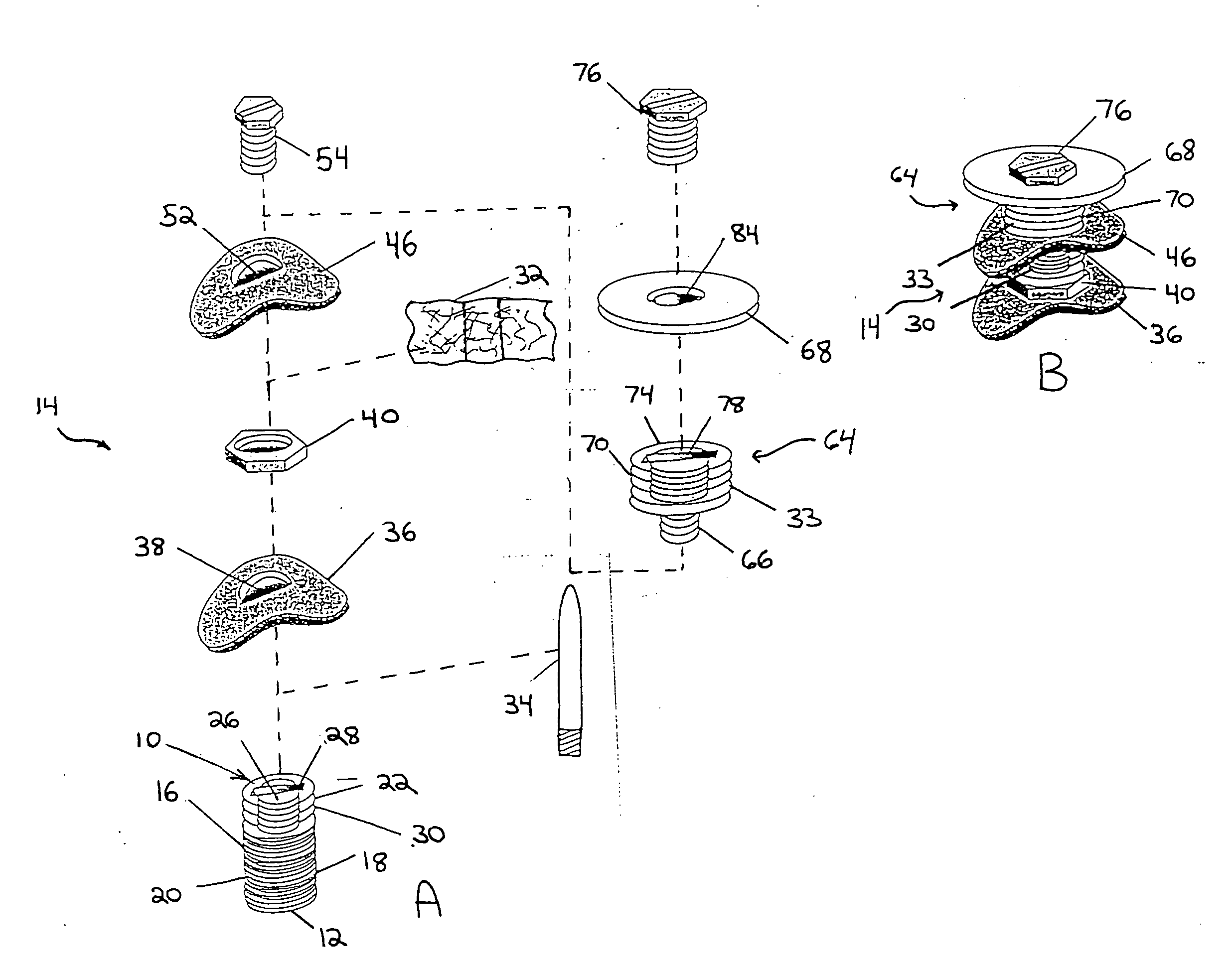
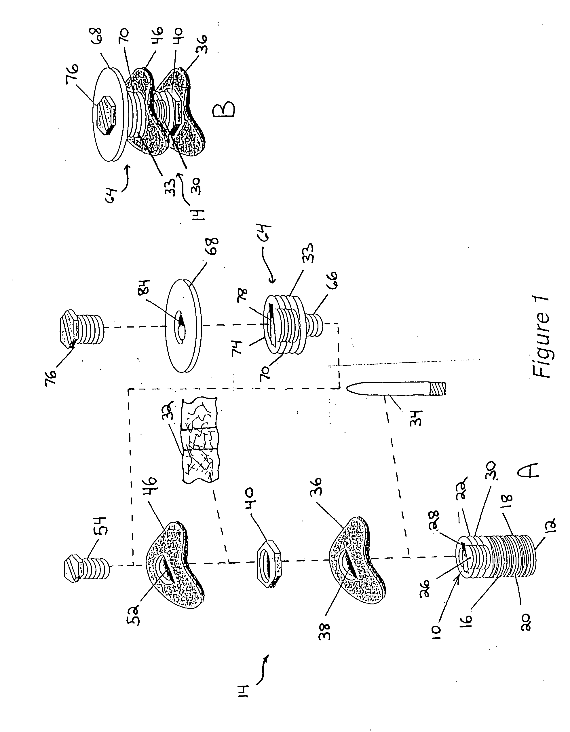
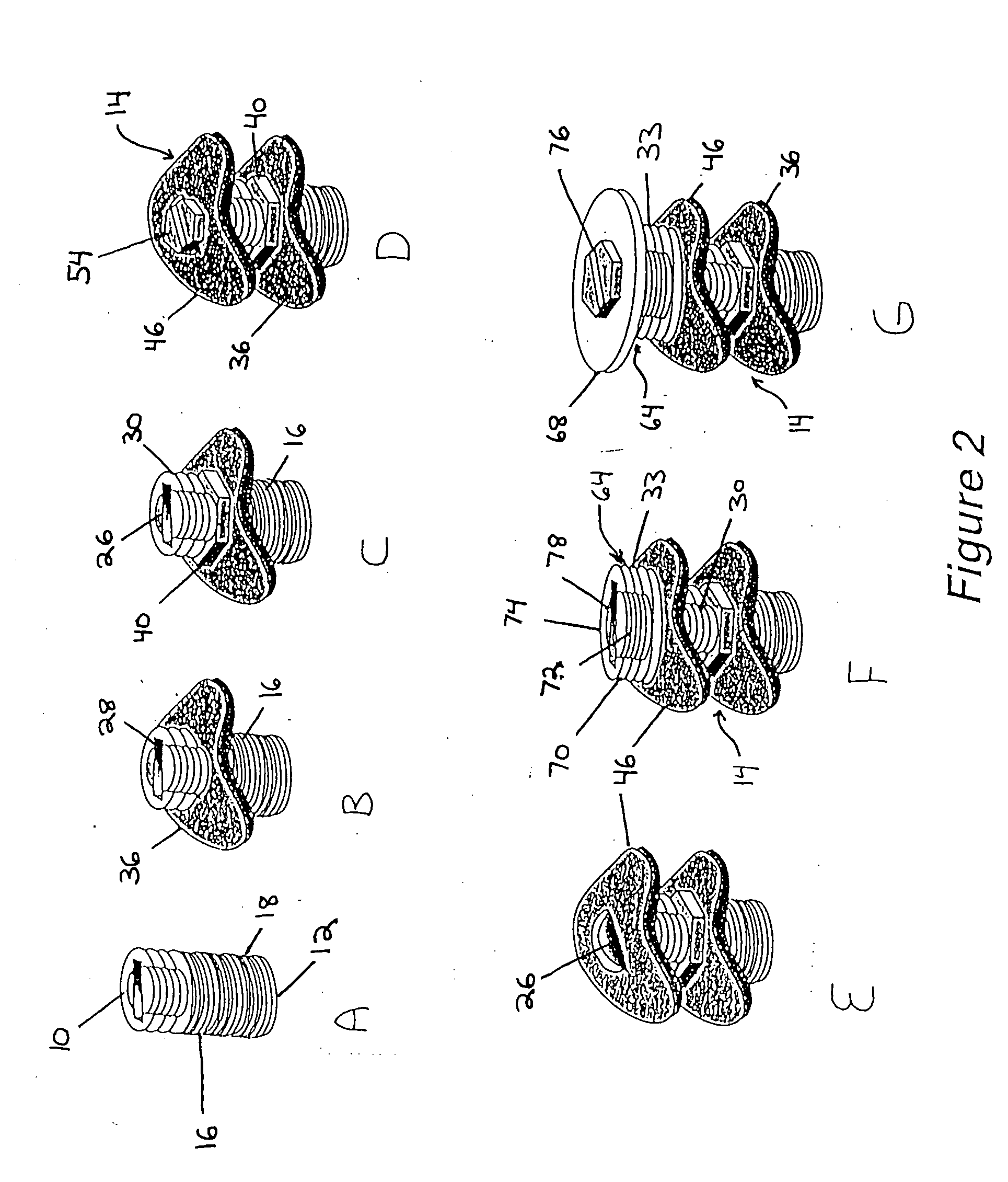
[0035] The implant in one embodiment of the invention as illustratively shown in FIG. 1 has a central axis (not shown) extending between a coronal end 10 and an apical end 12. The implant includes a level I assembly 10 having an initial implant portion 16 with an anchor portion 18. The anchor portion 18 may be substantially axially symmetric to the central axis. The anchor portion 18 has an exterior surface. In one embodiment the anchor portion 18 exterior surface has fastening means such as screw threads 20 helically disposed thereon. The threads advantageously have a minimal spacing, for example, less than 1 mm, and are self-tapping for optimal engagement and adaptation to existing alveolar bone. Other fastening means may be disposed on the anchor portion 18 exterior surface to help secure the anchor portion 18 to existing bone. The anchor portion 18 may for example be between about 3 mm and about 6 mm in length. The initial implant portion 16 may also have a transmucosal portion ...


PUM

PropertyMeasurementUnit
Biological propertiesaaaaaaaaaa
Bioavailabilityaaaaaaaaaa
Bioabsorbableaaaaaaaaaa

Abstract

A structural/biological implant and method of use. The implant being utilized as a single or multiple staged system that is designed to encourage new alveolar bone growth with or without the need to obtain autologous bone. The implant has an apical portion that is fastened into existing bone, with the remainder of the implant left outside of existing bone. The exposed portion of the implant may have an external shape or configuration with a variety of attached and/or integrally formed mechanical retention and stability elements. Osteotropic/angiotropic material may be associated with the implant to induce and or conduct new bone growth and possible vascularization, thus, rather than fitting the implant into the bone, the bone is grown integratively with the implant. The osteotropic/angiotropic materials may be simultaneously placed with the staged implant to provide consistent stabilization for the materials and to provide an immediately available surface for bone cell adhesion and growth. The invention thus allows implants to be used in location where the volume and/or shape of the bone would not be adequate for existing implant systems.

Description

CROSS REFERENCE TO RELATED APPLICATIONS [0001] This application claims the benefit of U.S. Provisional Application No. 60 / 478,705, filed Jun. 13, 2003, the content of which is incorporated by reference in their entirety.STATEMENT REGARDING FEDERALLY SPONSORED RESEARCH OR DEVELOPMENT [0002] This invention was made with Government support under Grant No. DE14187 awarded by the National Institute of Dental and Craniofacial Research. The Government has certain rights in the invention.FIELD OF THE INVENTION [0003] This invention relates generally to a structural / biological implant and method for encouraging bone growth with or without use of graft materials which may include autogenous bone, autologous or engineered cells, mineralized materials, demineralized bone matrix, alginates, collagen materials, and articles useful therein. BACKGROUND OF INVENTION [0004] Inadequate bone volume is a well recognized problem in the craniofacial and orthopedic fields. For example, ordinarily, a dental...

Claims


Application Information

Patent Timeline
IPC IPC(8): A61B17/68A61B17/80A61C8/00A61F2/28A61LA61L27/32A61L27/54A61L27/56A61L27/58
CPCA61B17/68A61B17/80A61C8/0006A61L27/32A61L2300/412A61L27/56A61L27/58A61L2300/252A61L2300/258A61L27/54A61L2430/02
Inventor FREILICH, MARTIN ALLENKELLY, JOHN ROBERTCOCHRANE, REBECCA LEE
Owner UNIV OF CONNECTICUT
Why Eureka
Try Eureka