Data hiding via phase manipulation of audio signals

a phase manipulation and audio signal technology, applied in the field of data hiding via phase manipulation of audio signals, can solve the problems of difficult steganography of digital audio signals, weak steganography, and insufficient offer technologies from digimarc and its competitors, and achieve the effect of preventing further illegal distribution of downloaded files

a phase manipulation and audio signal technology, applied in the field of data hiding via phase manipulation of audio signals, can solve the problems of difficult steganography of digital audio signals, weak steganography, and insufficient offer technologies from digimarc and its competitors, and achieve the effect of preventing further illegal distribution of downloaded files

US20050033579A1Active Publication Date: 2005-02-10MZ AUDIO SCI LLC

Image

  • Data hiding via phase manipulation of audio signals
  • Data hiding via phase manipulation of audio signals
  • Data hiding via phase manipulation of audio signals

Examples


Embodiment Construction

Two preferred embodiments and variations thereon will be set forth in detail with reference to the drawings.

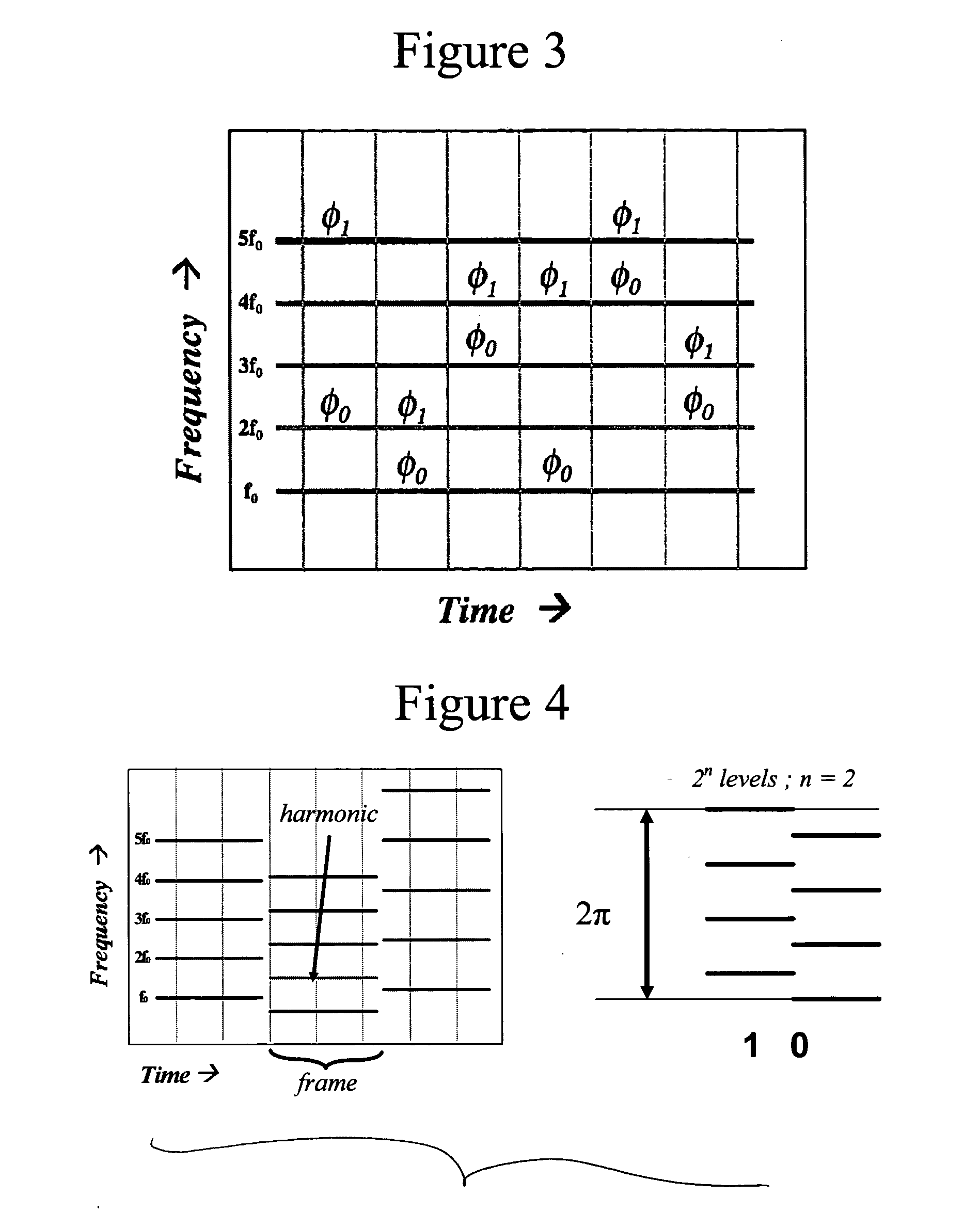
A first method of phase encoding is indicated in FIG. 3. In the illustrated method, during each time frame one selects a pair (or more) of frequency components of the spectrum and re-assigns their relative phases. The choice of spectral components and the selected phase shift can be chosen according to a pseudo-random sequence known only to the sender and receiver. To decode, one must compute the phase of the spectrum and correlate it with the known pseudo-random carrier sequence.

More specifically, a phase encoding scheme is indicated in which information is inserted as the relative phase of a pair of partials φ0, φ1 in the sound spectrum. In each time frame a new pair of partials may be chosen according to a pseudo-random sequence known only to the sender and receiver. The relative phase between the two chosen spectral components is then modified according to a pseudo-ra...


PUM


Abstract

Data are embedded in an audio signal for watermarking, steganography, or other purposes. The audio signal is divided into time frames. In each time frame, the relative phases of one or more frequency bands are shifted to represent the data to be embedded. In one embodiment, two frequency bands are selected according to a pseudo-random sequence, and their relative phase is shifted. In another embodiment, the phases of one or more overtones relative to the fundamental tone are quantized.

Description

FIELD OF THE INVENTION The present invention is directed to a system and method for insertion of hidden data into audio signals and retrieval of such data from audio signals and is more particularly directed to such a system and method using a phase encoding scheme. DESCRIPTION OF RELATED ART Digital watermarking currently is receiving a great amount of attention due to commercial interests that seek to control the distribution of digital media as well as other types of digital data. A watermark is data that is embedded in a media or document file that serves to identify the integrity, the origin or the intended recipient of the host data file. One attribute of watermarks is that they may be visible or invisible. A watermark also may be robust, fragile or semi-fragile. The data capacity of a watermark is a further attribute. Trade-offs among these three properties are possible and each type of watermark has its specific use. For example, robust watermarks are useful for establishi...

Claims


Application Information

Patent Timeline
10 Feb 2005
Publication
US20050033579A1
IPC
G10L19/00
CPC
G10L19/018
Inventors
BOCKO, MARK F.; IGNJATOVIC, ZELJKO