

Washing machine
a washing machine and apparatus technology, applied in other washing machines, cleaning using liquids, textiles and paper, etc., can solve the problems of increasing the overall size of the washing machine and wasting water, and achieve the effects of reducing the overall size and the amount of water, reducing power consumption, and shortening the washing tim
- Summary
- Abstract
- Description
- Claims
- Application Information
AI Technical Summary
Benefits of technology
Problems solved by technology
Method used
Image

Examples
second embodiment
[0059]FIG. 7 is a sectional view of a back-current preventing branch unit in accordance with the present invention.
[0060] A back-current preventing branch unit 80 in accordance with a second embodiment of the present invention includes a steam supply unit 82 connected to the steam supply line 34 and provided with steam; a circulation water supply unit 84 branched from the steam supply unit 82 at a predetermined angle, connected to the circulation line, and provided with circulation water; a nozzle connection unit 86 communicating with the steam supply unit 82 and the circulation water supply unit 84 so as to be connected with the spray nozzle 26; and a partition wall 83 formed in a longitudinal direction at the center of the nozzle connection unit and partitioning a steam supply passage and a circulation water supply passage.
[0061] The partition wall 83 divides the nozzle connection unit 86 into two parts at a position where the steam supply unit 82 and the circulation water supply...
third embodiment
[0062]FIG. 8 is a sectional view of a back-current preventing branch unit in accordance with the present invention.
[0063] A back-current preventing branch unit 94 in accordance with a third embodiment of the present invention includes a first supply unit 96 connected to one of the steam supply line 34 and the circulation line 38 and supplying steam or circulation water directly to the spray nozzle 26, and a second supply unit 98 branched at a predetermined angle from one side of the first supply unit 96 and supplying the other remaining one to the spray nozzle 26.
[0064] The first supply unit 96 is formed linearly and supplies one of steam and circulation water directly to the spray nozzle 26, and the second supply unit 98 is branched at a predetermined angle from one side of the first supply unit 96 to supply the other remaining one to the spray nozzle 26, thereby preventing steam or circulation water from flowing backward.
[0065] Preferably, the second supply unit 98 is disposed t...
fourth embodiment
[0066]FIG. 9 is a sectional view of a spray device of a washing machine in accordance with the present invention, FIG. 10 is an enlarged view showing a portion ‘A’ of FIG. 9, and FIG. 11 is a sectional view taken along line XI-XI of FIG. 9.
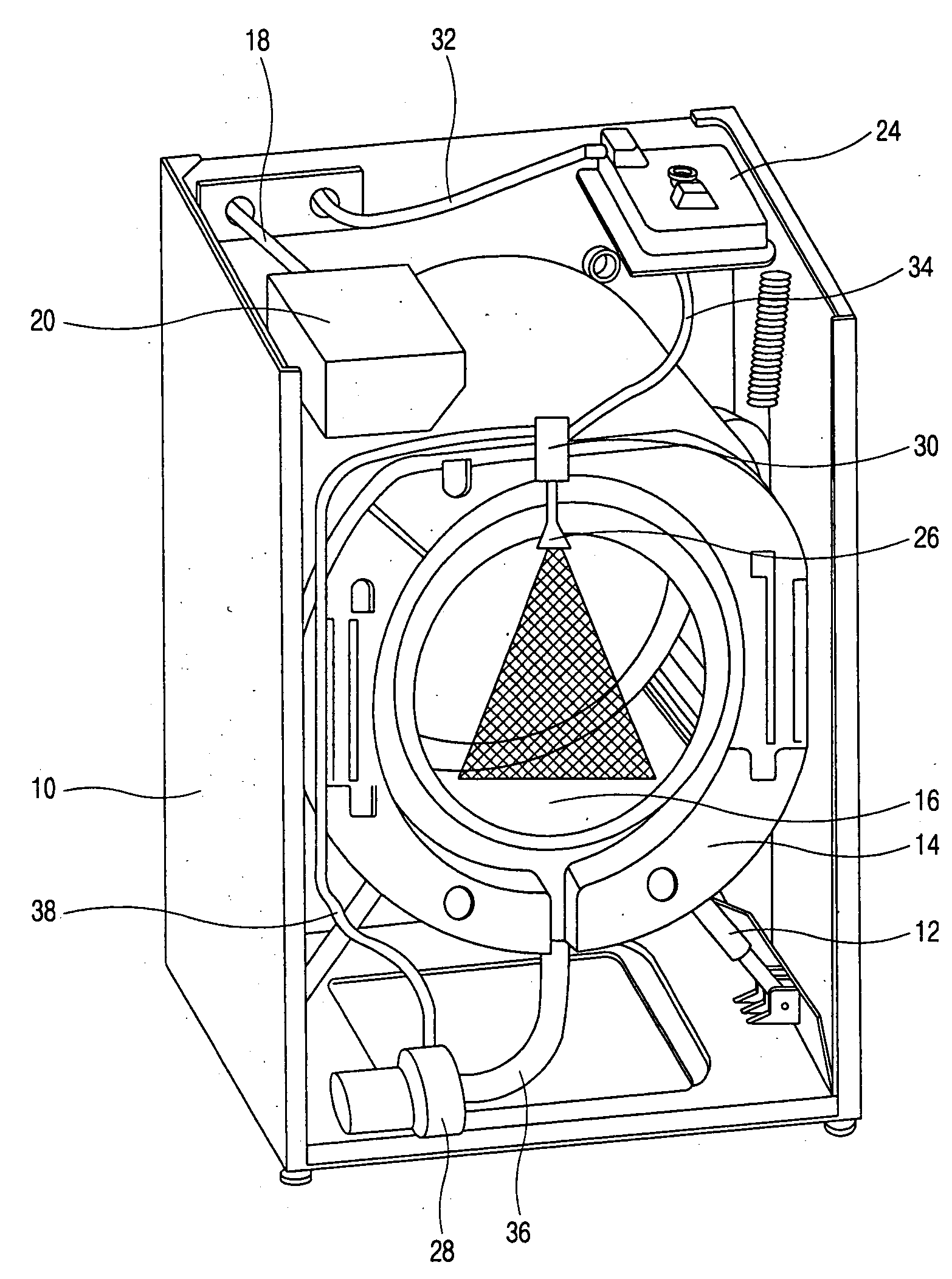
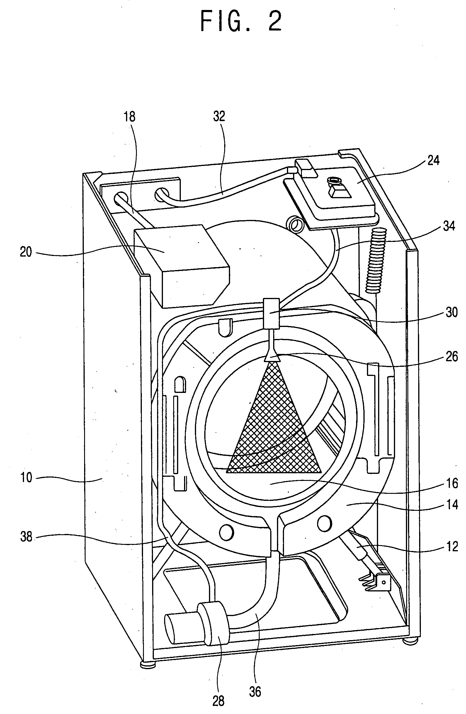
[0067] A washing machine in accordance with the fourth embodiment of the present invention includes a steam generator 24 for generating steam, a circulation pump 28 for pumping circulation water discharged from the tub 14 and re-supplying the circulation water into the drum 16; and a spray device 150 connected to the steam generator 24 by the steam supply line 34 and to the circulation pump 28 by the circulation line 38, and spraying either steam or circulation water into the drum.
[0068] The spray device 150 includes a main body 152 connected to the steam supply line 34 and the circulation line 38, a spray unit 154 formed at an end portion of the main body 152 and spraying either steam or circulation water into the drum 16; a steam passage 156 fo...
PUM
 Abstract
Description
Claims
Application Information