
Apparatus and method for acoustic position logging ahead-of-the-bit

a technology of acoustic position and acoustic recording, which is applied in the direction of instruments, surveying, and well accessories, etc., can solve the problems of not providing for determining images, affecting the accuracy of acoustic recording,

Inactive Publication Date: 2005-02-17
BAKER HUGHES INC
View PDF25 Cites 98 Cited by
  • Summary
  • Abstract
  • Description
  • Claims
  • Application Information

AI Technical Summary

Problems solved by technology

This type of measurement does not provide for determining an image of subsurface formation reflectors before the drill bit has reached the reflectors.
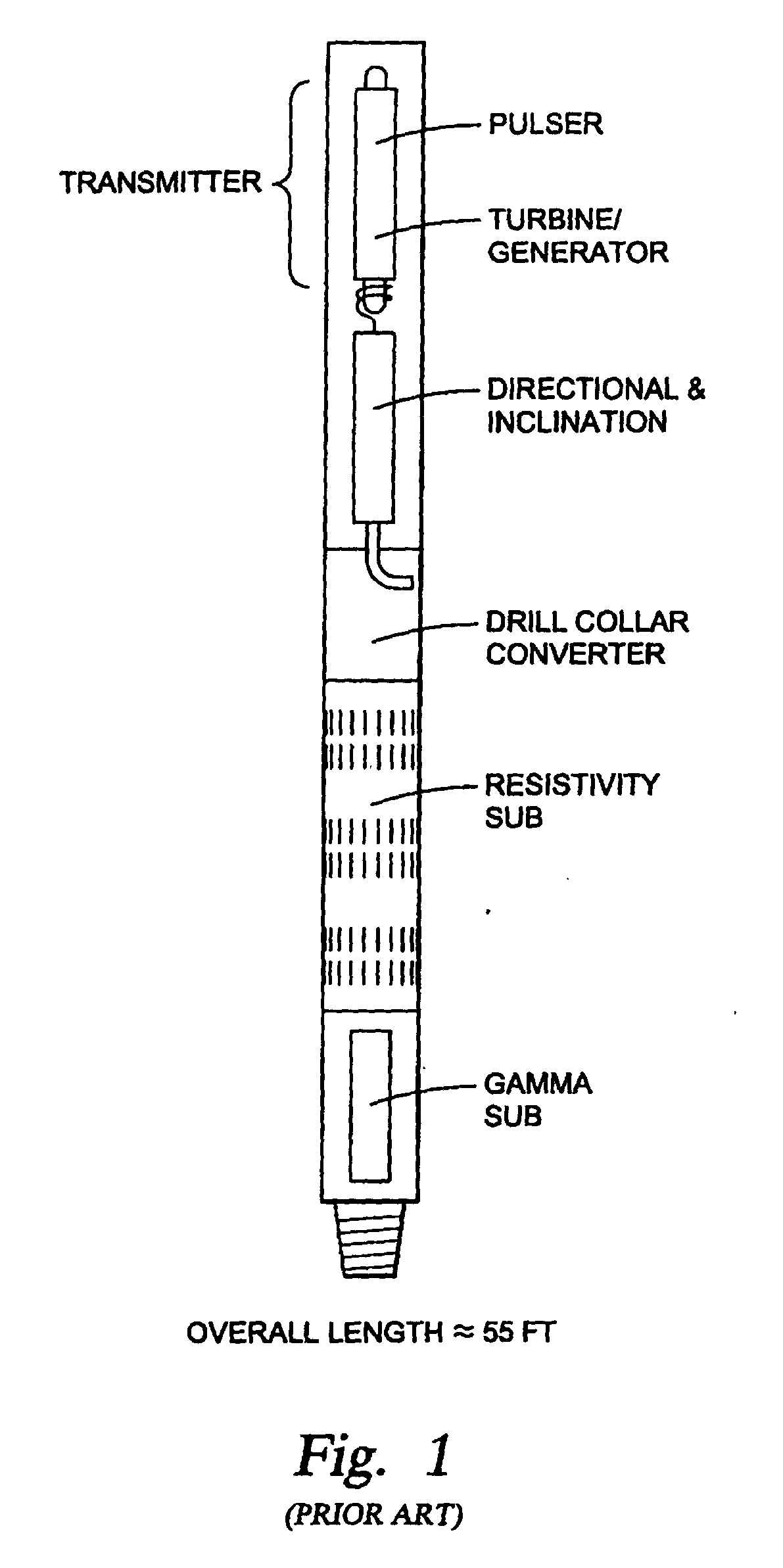
The multiple acoustic array arrangements provide for determining bed boundaries adjacent to the tool, as the tool traverses adjacent to the earth formation, but this arrangement is impractical for imaging ahead of the BHA in the direction of drilling.
According the disclosure, a disadvantage of the method is that events at a wide angle to the bit will be attenuated.

Method used


Image

  • Apparatus and method for acoustic position logging ahead-of-the-bit
  • Apparatus and method for acoustic position logging ahead-of-the-bit
  • Apparatus and method for acoustic position logging ahead-of-the-bit

Examples


Embodiment Construction

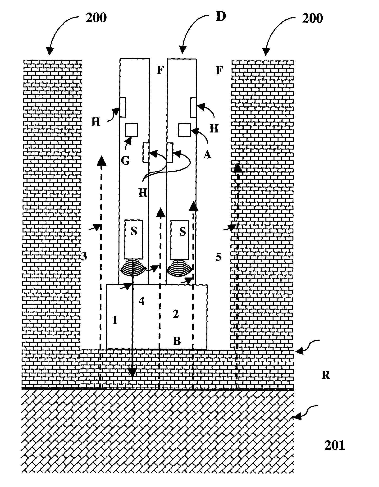
[0030] The present invention provides a method and system for using an acoustic logging tool conveyed in a borehole in an earth formation for determining a characteristic of the formation.

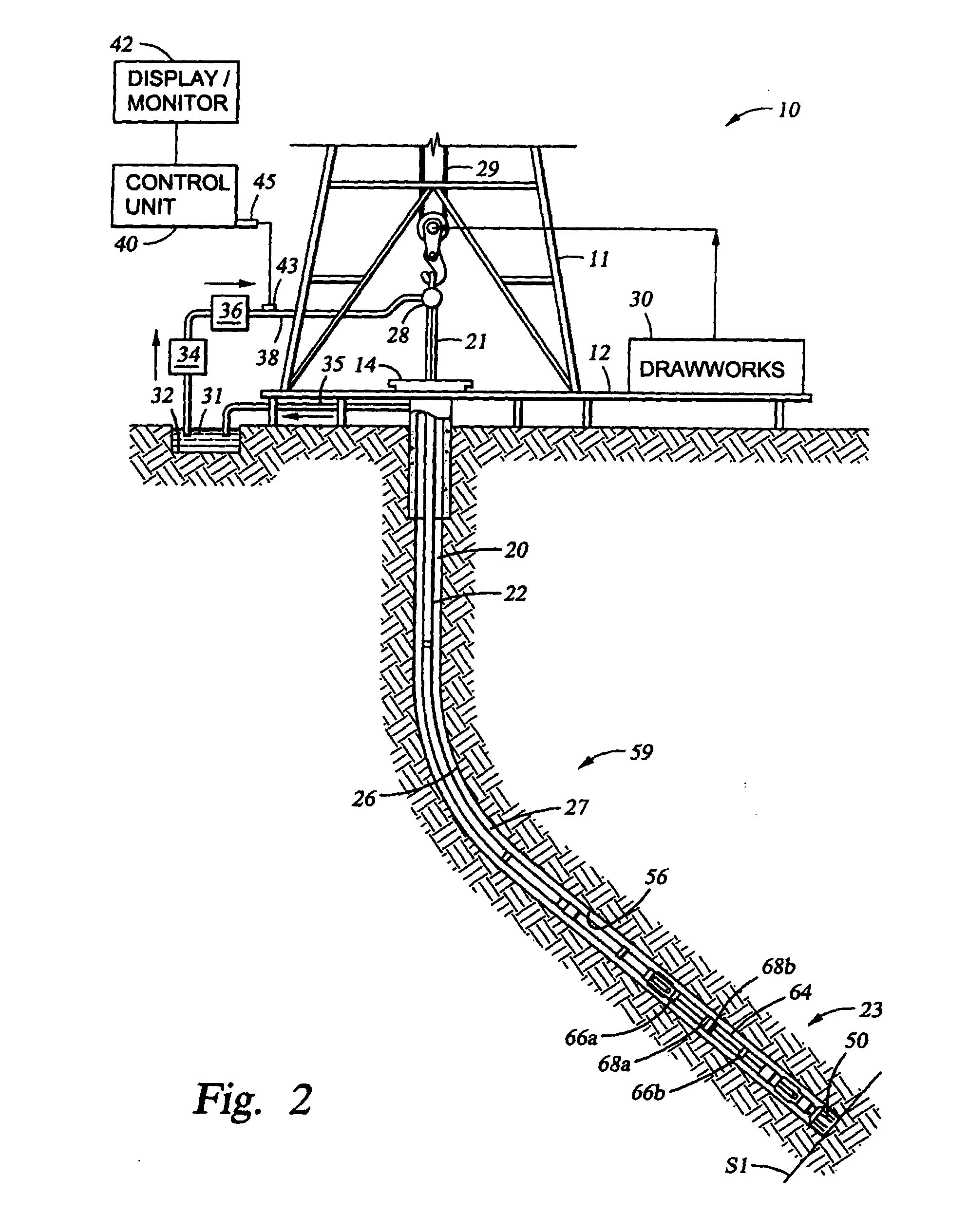
[0031]FIG. 2 shows a schematic diagram of a drilling system 10 having a downhole assembly containing a downhole sensor system and the surface devices according to one embodiment of present invention. As shown, the system 10 includes a conventional derrick 11 erected on a derrick floor 12 which supports a rotary table 14 that is rotated by a prime mover (not shown) at a desired rotational speed. A drill string 20 that includes a drill pipe section 22 extends downward from the rotary table 14 into a borehole 26. A drill bit 50 attached to the drill string downhole end disintegrates the geological formation 23 when it is rotated. The drill string 20 is coupled to a drawworks 30 via a kelly joint 21, swivel 28 and line 29 through a system of pulleys (not shown). During the drilling operations, the dra...


PUM


Abstract

The present invention provides a method and apparatus for acoustic position logging ahead of a drill bit. The method and apparatus comprise a bottomhole assembly (BHA) conveyed on a drilling tubular in a borehole within an earth formation. The BHA has a source array for emitting preselected acoustic signals into the earth formation, and at least one receiver on the BHA for receiving a second acoustic signal produced by an interaction of the preselected acoustic signal with said formation. The source array for acoustic energy may be configured as an axially distributed array of axially or azimuthally directed sources, or an azimuthally distributed array of axially or azimuthally directed sources. The sources may be activated according to preselected time delays. The emitted acoustic signal is differing in spectrum and / or wave mode from the acoustic energy of a rotating drill string.

Description

FIELD OF THE INVENTION [0001] The present invention is related to the field of geophysical exploration and more specifically to a method of using a seismic source to generate and acquire directional signals in a wellbore during drilling operations. BACKGROUND OF THE INVENTION [0002] In the oil and gas industry, geophysical prospecting techniques are commonly used to aid in the search for and evaluation of subterranean hydrocarbon deposits. Generally, a seismic energy source is used to generate a seismic signal which propagates into the earth and is at least partially reflected by subsurface seismic reflectors (i.e., interfaces between underground formations having different acoustic impedances). The reflections are recorded by seismic detectors located at or near the surface of the earth, in a body of water, or at known depths in boreholes, and the resulting seismic data may be processed to yield information relating to the location of the subsurface reflectors and the physical prop...

Claims


Application Information

Patent Timeline
Patent Type & Authority Applications(United States)
IPC IPC(8): E21B47/14G01V1/00G01V1/40G01V1/44
CPCG01V1/44
Inventor MATHISZIK, HOLGEROPPELT, JOACHIM
Owner BAKER HUGHES INC
Learn More