Continuous magnetic seperator and process

a magnetic seperator and process technology, applied in the direction of magnetic separation, separation process, filtration separation, etc., can solve the problems of limiting the use of batch filtration process in an otherwise continuous reaction system, and affecting the efficiency of the process

Inactive Publication Date: 2005-02-17
RES USA LLC
View PDF23 Cites 46 Cited by
  • Summary
  • Abstract
  • Description
  • Claims
  • Application Information

AI Technical Summary

Problems solved by technology

In the past, solids separation in slurry phase Fisher-Tropsch systems has involved complex mechanical filtration systems performed outside the slurry reactor.
This reactor has the difficulty of added operation constraints to control the filter elements and need for occasional back flushing.
However, the use of a batch filtration process is undesirable in an otherwise continuous reaction system.
Conventional HGMS methods are restricted when the concentration of magnetics in the feed exceeds this range, because of excessive capture-matrix loading which leads to poor non-magnetics weight yields.
Application of carousel as described in Marston (U.S. Pat. No. 3,920,543) and reciprocating as discussed in “Coal Preparation Using Magnetic Separation,” Volume 2, CS-1517, Volume 2 Research Project 980-2 Prepared by Magnetic Corporation of America, Z. J. J. Stekly, Principal Investigator, which are hereby incorporated herein by reference, show that HGMS units will be problematical for the Fischer-Tropsch application because of the complexity of the apparatus and incompatibility with high temperature and high pressure.
Thus the use of this separator is limited to separation of emulsified liquid phases and the means for controlling the outlet flows was limited to controlling the depth of a “magnetic plug” of the coalesced phase as would apply to a liquid-liquid separation.
An ideal device would look very much like a continuous settler, though those skilled in the art will appreciate that sedimentation is not generally practical for separating fine particles in a pressurized system since the separation rates are often be too low resulting in the need for too large a pressurized sedimentation vessel to be practical.

Method used


Image

  • Continuous magnetic seperator and process
  • Continuous magnetic seperator and process
  • Continuous magnetic seperator and process

Examples


example 1

Testing of a Continuous Magnetic Separator—Room Temperature Tests on a Continuous Magnetic Separator Using an External Electromagnet

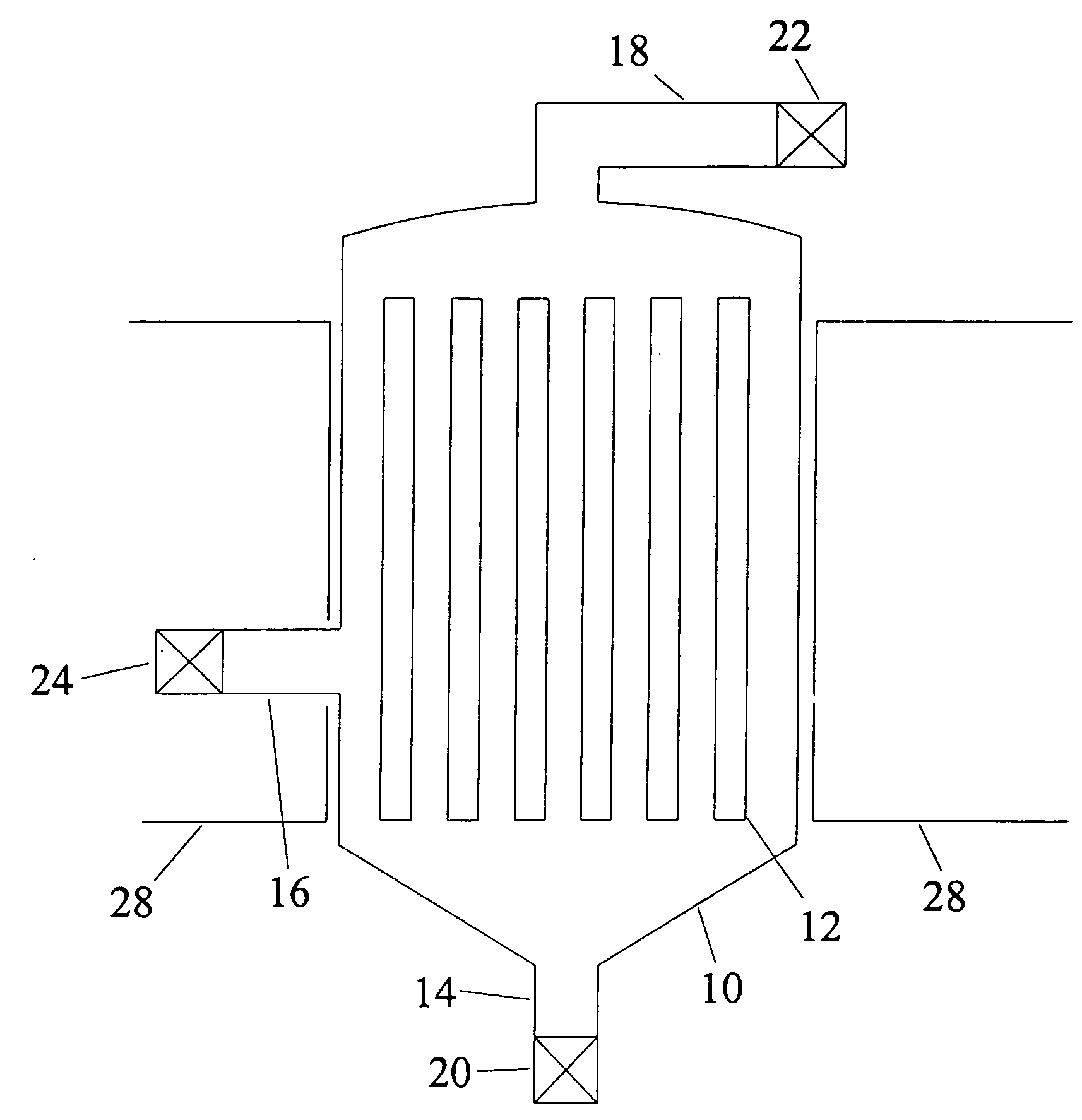
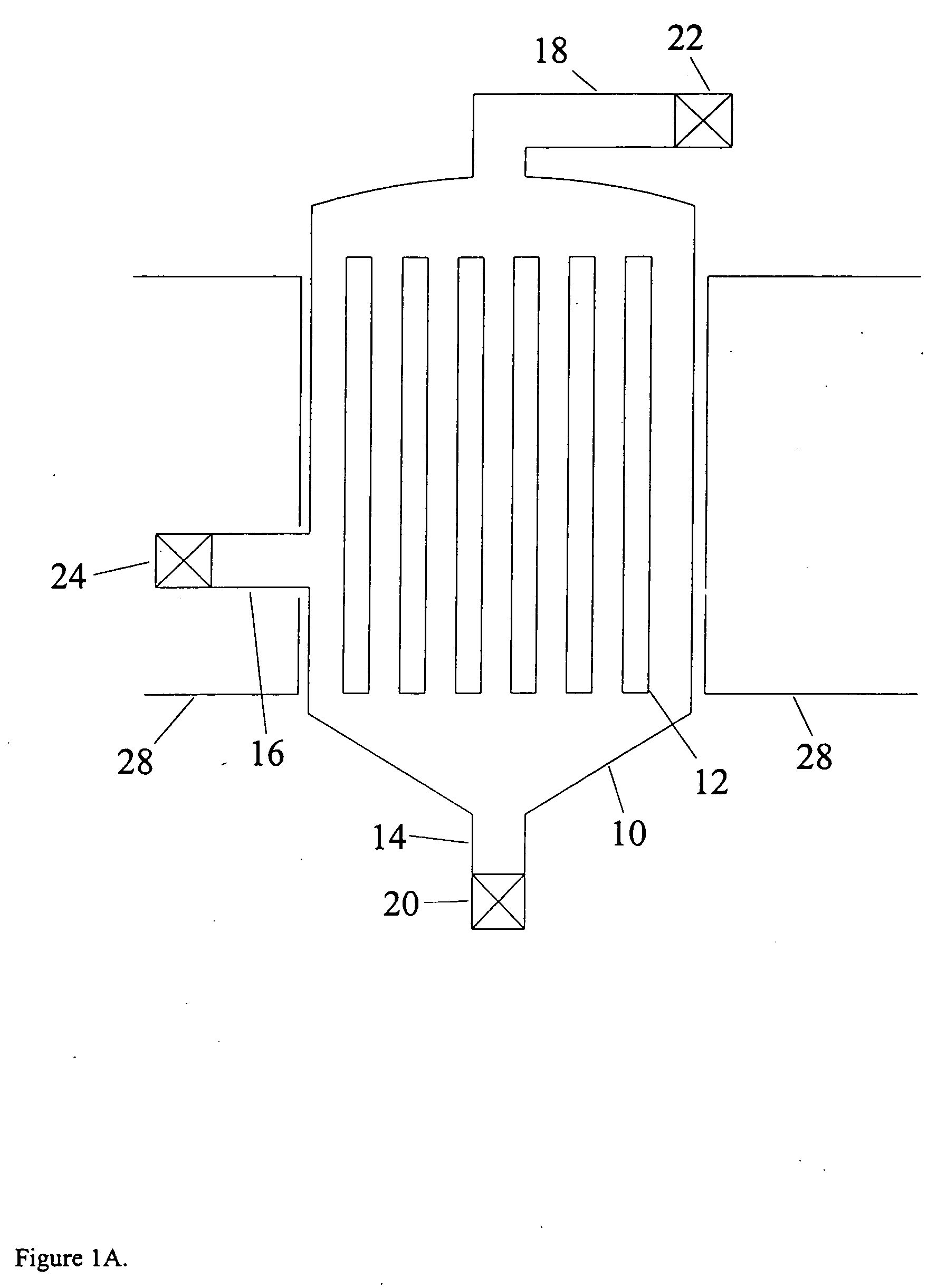
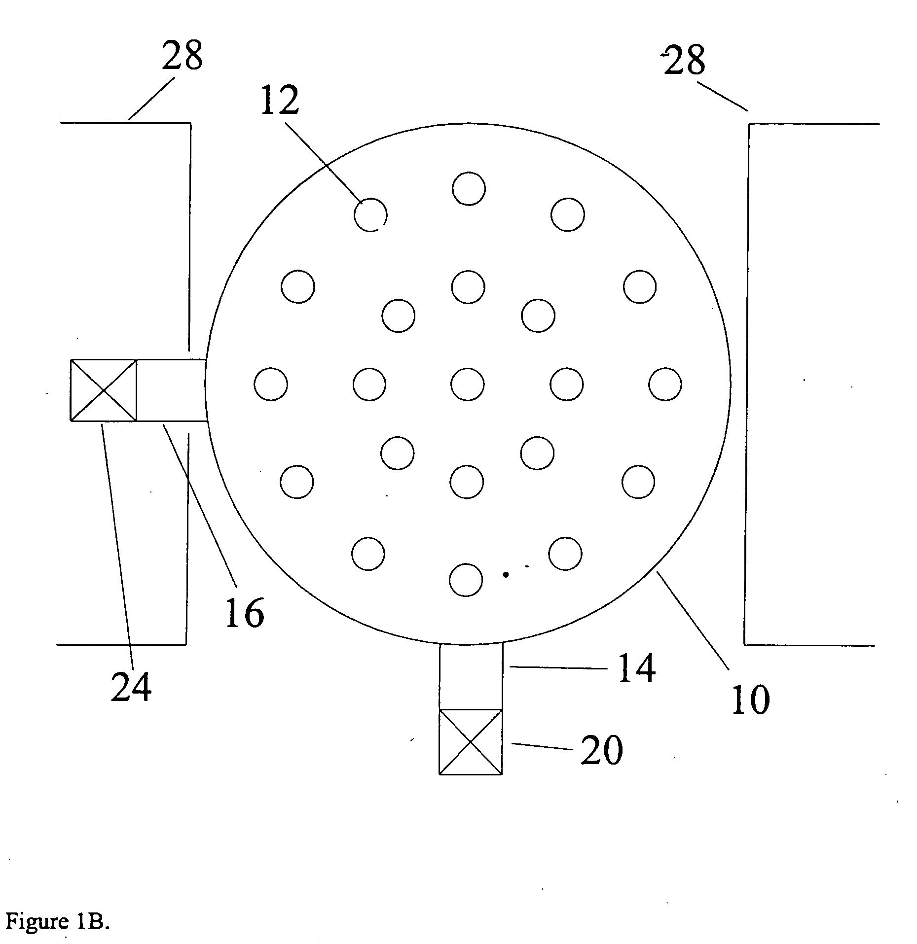
A continuous magnetic separator was tested in the laboratory at conditions chosen to simulate a Fischer-Tropsch reaction slurry. The tests were run with an iron-based catalyst that is a precipitated iron catalyst with a atomic ratio of 100 Fe: 4.4 Si. The catalyst was supplied in the unactivated form. Hexadecane was chosen to be used as an analog liquid for room temperature experiments. The analog was chosen to have a room temperature density and viscosity similar to the F-T waxes at process temperatures. Hexadecane has a density of 0.7733 g / ml, and a viscosity of 3.3 cP, which are very close to the densities (0.625-0.9317 g / ml) and viscosities (2.4-11.9 cP) for F-T waxes reported in the literature (see, Zhou, P. Z., “Status Review of Fischer-Tropsch Slurry Reactor Catalyst / Wax Separation Techniques,” Prepared by Burns and Roe Services Corporation for...

example 2

High Temperature Runs

Tests at 200° C. showed similar results to the room temperature results in Table 1, showing concentrations between about 0.1% and 0.3% catalyst in the clarified liquid for Recycle Ratios between R=5 and R=9 with 4 rods at a feed flow rate of 740 cm3 / min and a magnetic field of 2800 Gauss.

example 3

Separation with Permanent Magnets

A test of permanent magnets was made with a cell containing 4 alnico permanent magnets, 8 inches long and 0.125 inches OD. The catalyst concentration was reduced from 20% to 2% in that test. It is anticipated that substantially lower product concentrations will be achieved for an optimized system, comparable to those obtained with a external magnet.


PUM

PropertyMeasurementUnit
diametersaaaaaaaaaa
sizeaaaaaaaaaa
sizeaaaaaaaaaa

Abstract

A continuous magnetic separator and process for separating a slurry comprising magnetic particles into a clarified stream and a thickened stream. The separator has a container with a slurry inlet, an overflow outlet for the discharge of the clarified slurry stream, and an underflow outlet for the discharge of a thickened slurry stream. Magnetic particles in the slurry are attracted to, and slide down, magnetic rods within the container. The slurry is thus separated into magnetic concentrate and clarified slurry. Flow control means can be used to control the ratio of the rate of magnetic concentrate to the rate of clarified slurry. Feed control means can be used to control the rate of slurry feed to the slurry inlet.

Description

This invention was made with Government support under Grant DE-FG02-00ER83008 awarded by the United States Department of Energy. The Government has certain rights in this invention. BACKGROUND OF THE INVENTION 1. Field of the Invention This invention relates to an apparatus and methods for continuous separation of magnetic particles from a slurry. 2. Description of the Prior Art There are a number of circumstances where it would be desirable to continuously separate magnetic particles from a slurry. One example is separation of magnetic catalyst particles from a slurry in a slurry reaction system, such as a slurry phase Fisher-Tropsch synthesis wherein carbon monoxide and hydrogen are reacted to form hydrocarbons in the presence of an iron catalyst. The reactor contains a three phase mixture of gases and a slurry of fine catalyst particles in the hydrocarbons. The success of the iron-based process depends on the ability to economically separate the catalyst from the hydrocarbon...

Claims


Application Information

Patent Timeline
Patent Type & Authority Applications(United States)
IPC IPC(8): B01D35/06B03CB03C1/00B03C1/02
CPCB01D35/06B03C2201/18B03C1/286B03C1/032
Inventor ODER, ROBIN RJAMISON, RUSSELL E.
Owner RES USA LLC
Why Eureka
Try Eureka