Communication system

a communication system and communication technology, applied in the field of communication systems, can solve the problems of holding on to the above, and achieve the effect of low field intensity and low field intensity

Inactive Publication Date: 2005-02-17
MEDIAGRAM
View PDF4 Cites 37 Cited by
  • Summary
  • Abstract
  • Description
  • Claims
  • Application Information

AI Technical Summary

Benefits of technology

[0039] In the communication systems according to the first, third, and fifth aspects of the present invention, it is preferable that the ID read signal output from the reading means of the respective transmitter and receiver is an infrared signal, an ultrasonic signal, or a radiowave signal, and the signal-has a low field intensity.
[0040] Also, in the communication system according to the present invention, the wireless tag is preferably configured to output its own ID or ID segment in the form of an infrared signal, an ultrasonic signal, or a radiowave signal, and the signal-has a low field intensity, whereas the communication signal from the transmitter to the receiver is preferably a wireless communication signal.
[0041] Further, in the communication system according to the present invention, it is preferable that the transmitter and the receiver are a control apparatus and a target apparatus, or personal computers.

Problems solved by technology

Since repeated setting of an ID is time-consuming for an operator to perform, a need exists for a method of simply and automatically setting an ID each time a control apparatus or a target apparatus is replaced with another one.
The foregoing problem holds true not only in a remote control system comprised of control apparatuses and target apparatuses, but also in a general wired communication system and wireless communication system comprised of transmitters and receivers which communicate signals such as data in which an ID is multiplexed.

Method used


Image

  • Communication system
  • Communication system
  • Communication system

Examples


first embodiment

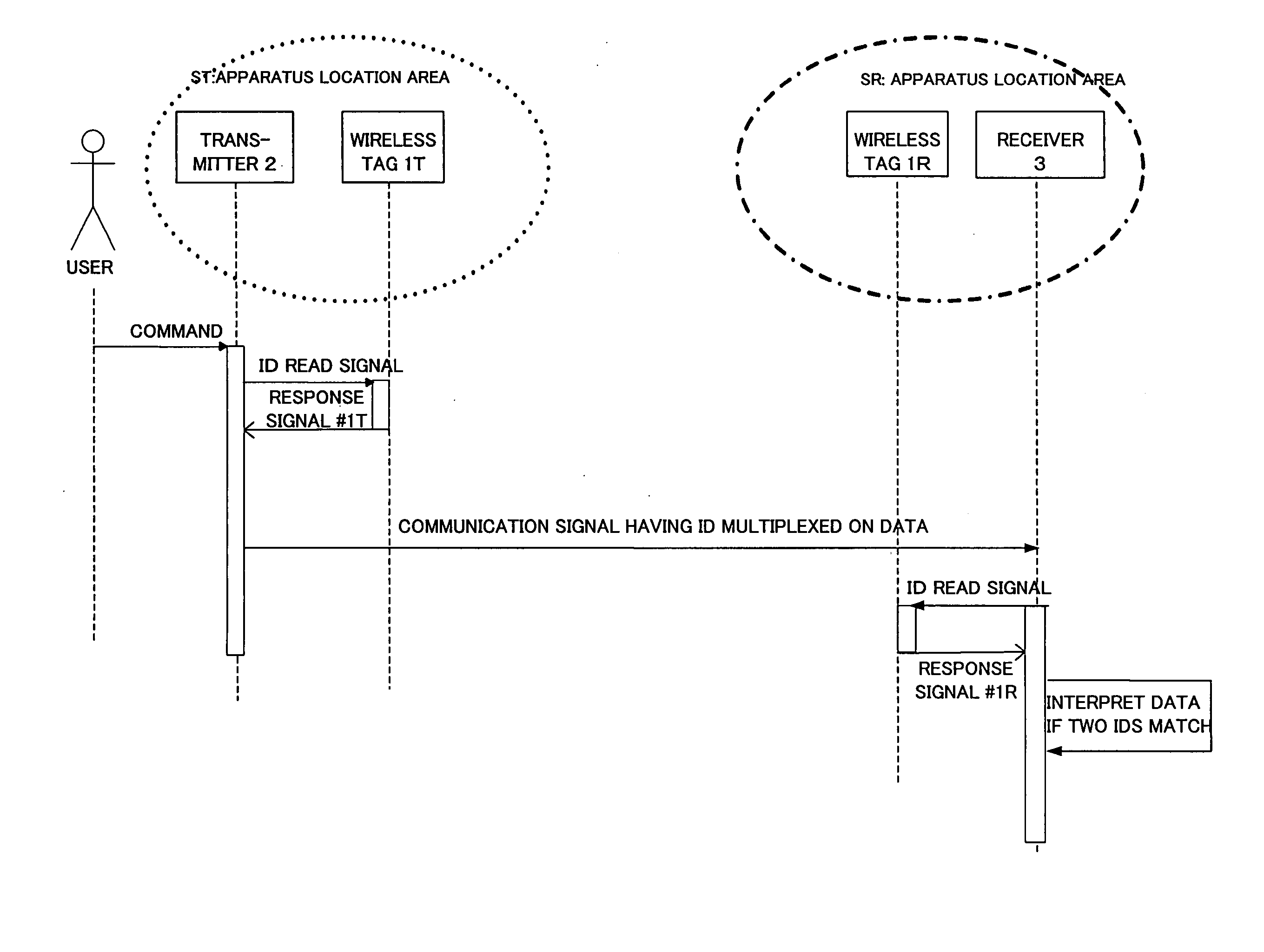
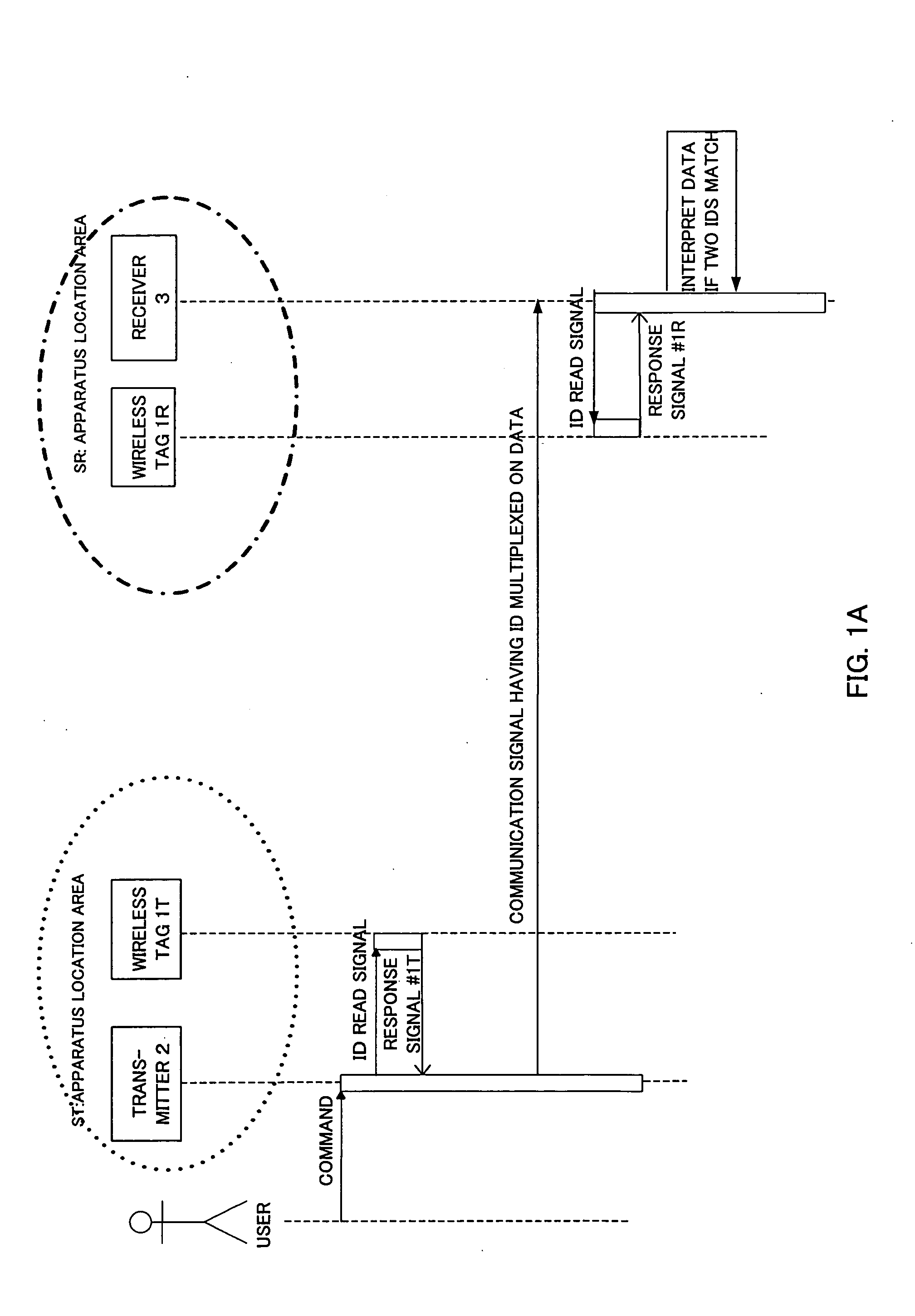
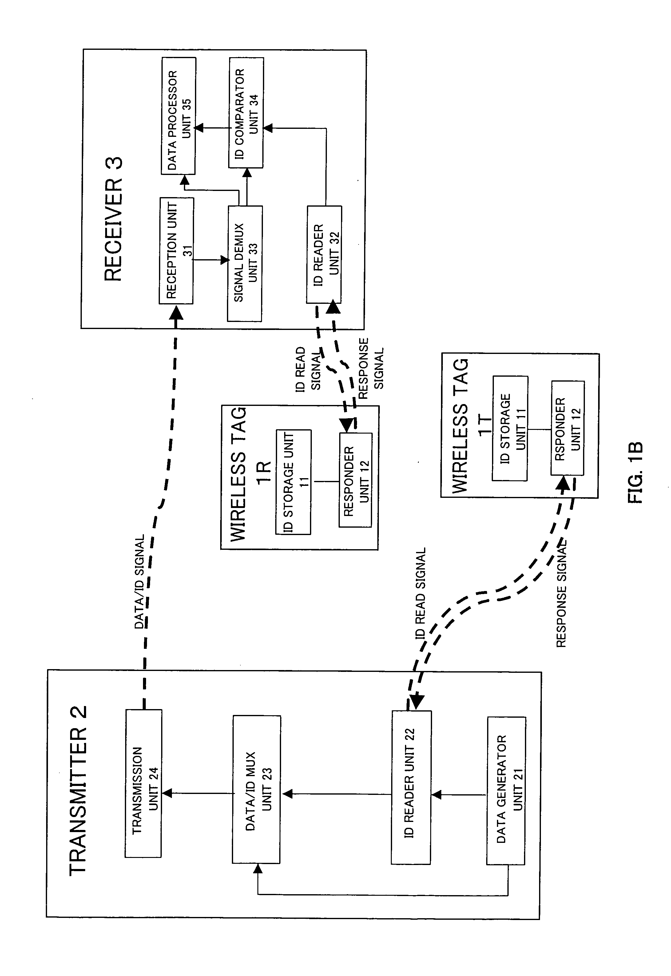
[0053]FIGS. 1A and 1B illustrate a communication system according to the present invention. In FIG. 1A, 1T and 1R denote wireless tags which are disposed at arbitrary locations such as on a ceiling, a wall, a floor, a desk and the like in buildings, and the numerals 2 and 3 denote a transmitter and a receiver. The wireless tags 1T and 1R store the same ID. The transmitter 2 transmits an ID read signal before transmitting data, and extracts an ID from a received response signal #1T returned from the wireless tag 1T in response to the ID read signal, multiplexes the read ID on the data to be transmitted, and transmits the data multiplexed with the ID. The receiver 3 in turn transmits an ID read signal upon receipt of a signal, extracts an ID from the signal, extracts an ID from a response signal #1R returned from the wireless tag 1R in response to the ID read signal, and compares the ID in the received signal with the ID read from the wireless tag 1R. In a case that the both IDs match...

third embodiment

[0076] Generally, a wireless tag can store a limited length of ID (the number of bytes of an encoded value(s)), so that when a long ID is necessary, it is necessary that it be divided. However, if one ID is simply divided into k sections which are assigned to and stored in k wireless tags, all the k wireless tags must be provided in each area (the transmitter location area or receiver location area) in order to restore the original ID. Further, when read errors of the wireless tags are taken into consideration, k wireless tags are not sufficient, and a number of wireless tags approximately twice as the value of k must be provided in the area. On the contrary, when the FEC coding is applied as in the present invention, a much smaller number of wireless tags are required proportional to expected read errors, as compared with the simple division of the ID.

[0077] In addition, when all wireless tags placed near the transmitter and receiver have different IDs, it is necessary to store a l...

second embodiment

[0093] According to the present invention, the foregoing problems can be solved as described below. FIGS. 6A and 6B illustrate an exemplary solution in which the present invention is applied to a remote control system for a television receiver set. It should be noted, however, that a transmitter location area matches with a receiver location area in this remote control system.

[0094] In FIGS. 6A and 6B, TV receiver sets 3A, 3B are placed in adjacent rooms A and B, respectively, and a remote control unit 2A can be used commonly for the TV receiver sets 3A and 3B. Wireless tags 1T1A, 1T2A, 1R1A, and 1R2A are fixed at locations such as on a wall surface, a ceiling, a floor, or the like of the room A, while wireless tags 1T1B, 1T2B, 1R1B, and 1R2B are fixed in a similar manner. While FIG. 6A illustrates an example in which four wireless tags are installed in each room, the number of the wireless tags is not limited to four, but an arbitrary number of wireless tags may be installed in eac...


PUM


Abstract

A communication system comprises one or a plurality of first wireless tags for defining a first apparatus location area, one or a plurality of second wireless tags for defining a second apparatus location area, a transmitter, and a receiver. The first and wireless tags store IDs corresponding thereto. The transmitter, when residing in the first or second apparatus location area, outputs a wireless ID read signal to read the ID of the wireless tag in the area, multiplexes the read ID on a communication signal, and transmits the resultant communication signal. The receiver, when residing in the second or first apparatus location area, outputs a wireless ID read signal to read the ID of the wireless tag in the area, determines whether or not an ID identical to the read ID is multiplexed on a received communication signal, and determines that the communication signal is addressed to the receiver itself when the ID is multiplexed. In this way, a signal from the transmitter residing in one of the first and second apparatus location areas can be received only by a receiver residing in the other apparatus location area. The wireless tags may be of active type to eliminate the read signal.

Description

BACKGROUND OF THE INVENTION [0001] The present invention generally relates to a communication system, and more particularly to a communication system which allows only an intended destination to appropriately receive a communication signal such as a control signal, a data signal, and so on. [0002] A remote control system using radio communication technologies occasionally needs to make settings to enable a particular control apparatus (or initiator) to remotely control a target apparatus, and to disable other control apparatuses to remotely control the target apparatus. In such a case, as described in the following References 1 and 2, a control apparatus multiplexes in a control signal an ID signal for identifying a target apparatus, and transmits the resulting multiplexed signal, while the target apparatus obtains the control signal multiplexed with the own ID signal from received signals, and performs a control operation in accordance with the control signal. [0003] The following ...

Claims


Application Information

Patent Timeline
Patent Type & Authority Applications(United States)
IPC IPC(8): G08C17/02G08C19/00G08C23/04H04B1/06H04L12/28H04N5/00H04Q9/00H04W4/04H04W84/10H04W84/12H04W92/08
CPCG08C17/02G08C2201/91G08C23/04
Inventor KIMURA, MAKOTO
Owner MEDIAGRAM
Why Eureka
Try Eureka