
Non-contact power feeding apparatus

Inactive Publication Date: 2012-06-21
SHOWA AIRCRAFT INDUSTRY
View PDF1 Cites 12 Cited by
  • Summary
  • Abstract
  • Description
  • Claims
  • Application Information

AI Technical Summary

Benefits of technology

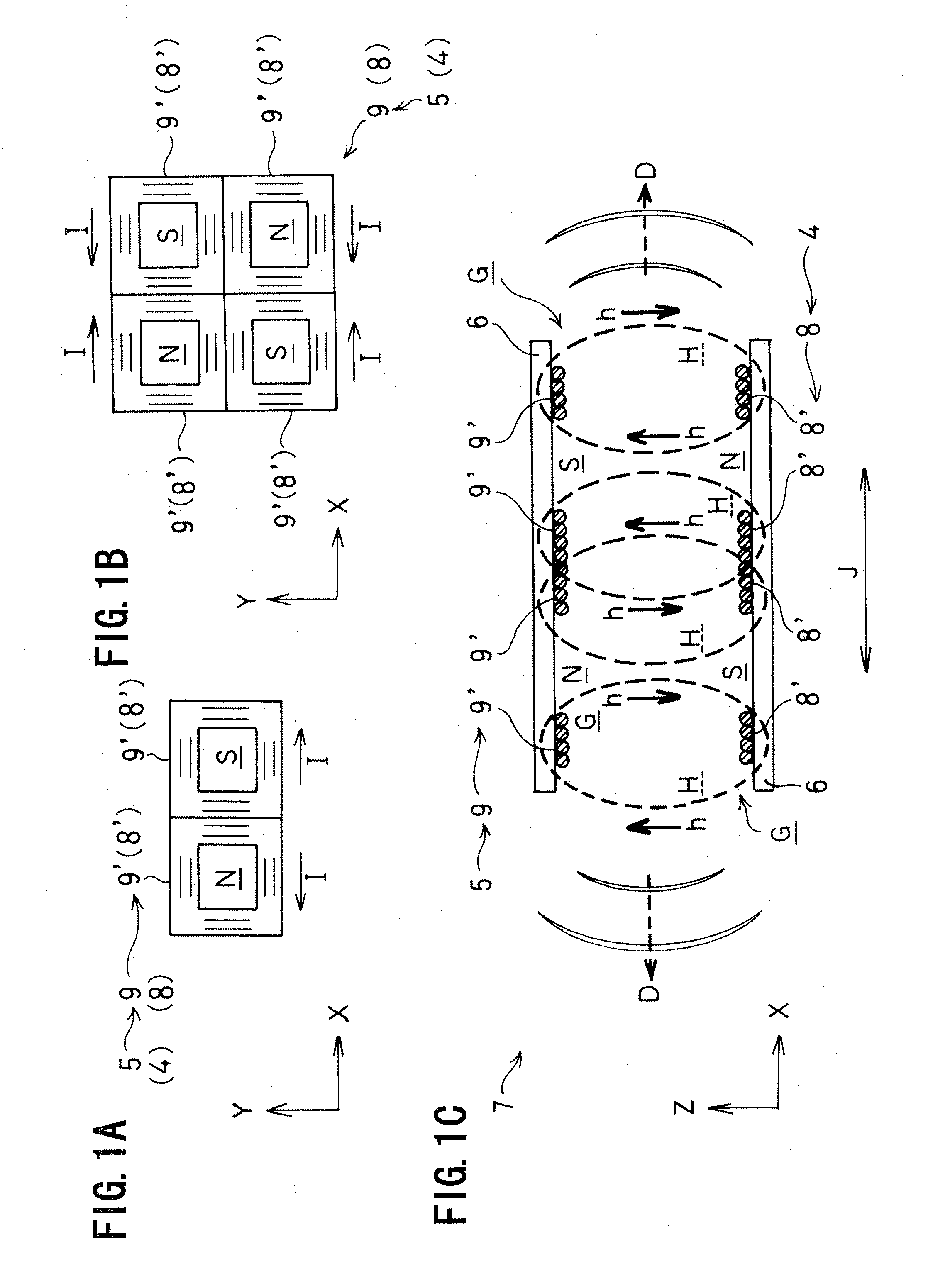
[0049]First, an electromagnetic disturbance can be prevented. In the non-contact power feeding apparatus of the present invention, the power transmission coil and the power receiving coil are provided with, for example, a 4-pole structure, an 8-pole structure or a multi-pole structure, and the direction of an electric current and the north and south poles are made in reverse between each unit coil which is juxtaposed to the other to directly come into line.
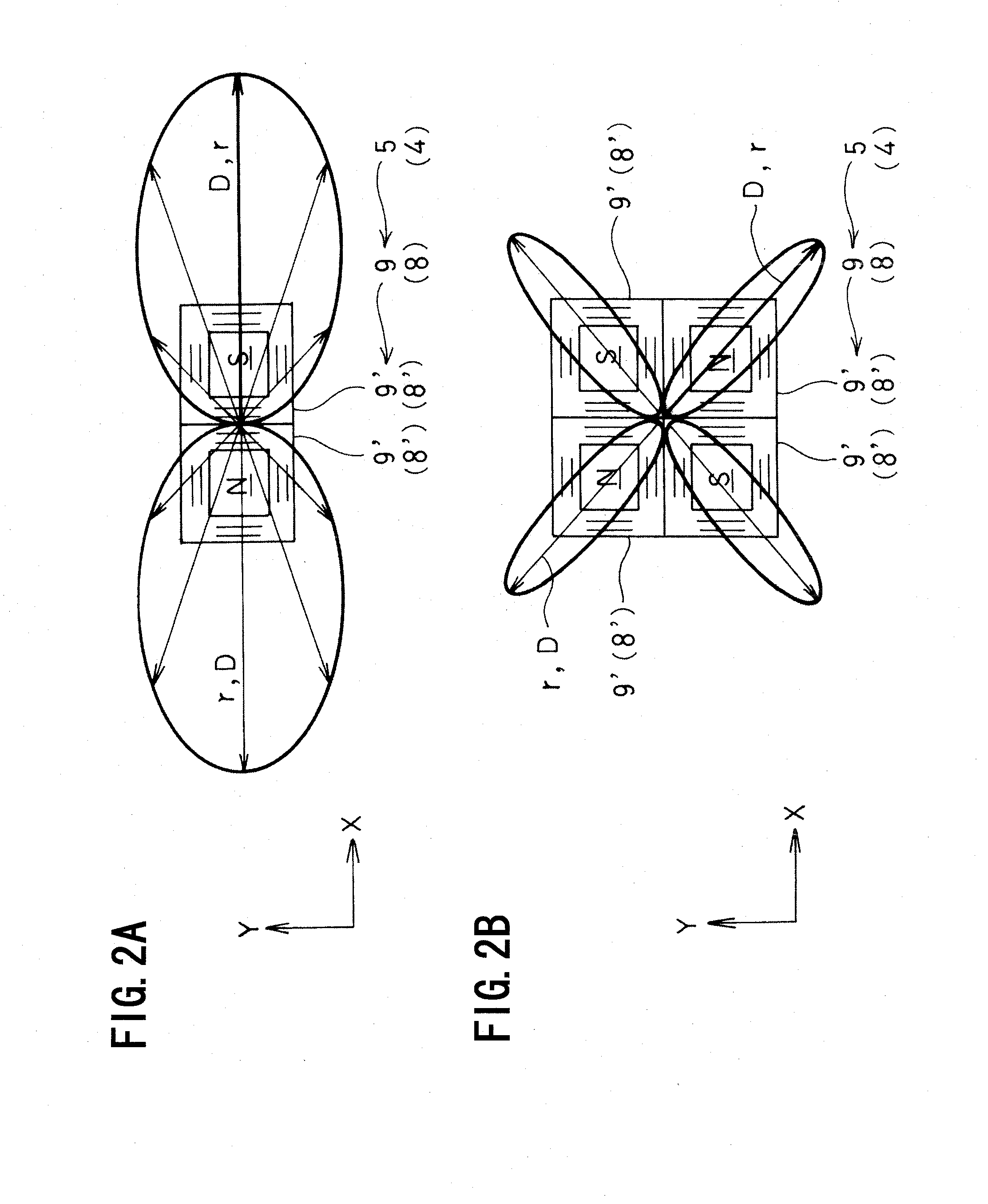
[0050]Since an overlapping area of the magnetic field respectively formed by the unit coil cancels another out and is weakened, the electromagnetic waves radiated to the outside are drastically reduced in total. In this manner, since the electromagnetic field radiation diffused to the outside to be spread is reduced and the electromagnetic field strength is lowered, a risk of causing the electromagnetic disturbance in the neighborhood can be prevented.
[0051]As in the conventional example of this type described above, the non-contact power feeding apparatus of the present invention can prevent a risk of generating electronic jamming or of producing a functional disorder to the human body in the area of, for example, tens of meters to hundreds of meters away.
[0053]Second, an air gap can be expanded. In the non-contact power feeding apparatus of the present invention, the electromagnetic waves radiated to the outside can be drastically reduced in total to prevent the possible electromagnetic disturbance.
[0054]As compared to the conventional example of this type described above, the non-contact power feeding apparatus of the present invention makes it possible to provide a larger air gap. Expansion of the air gap results in the increase of the exciting reactive power and the exciting apparent power, but the adverse effect can be covered (offset) by the first effect described above. In the non-contact power feeding apparatus, there is a great need for the expansion of air gap (i.e., realization of a large air gap) in view of the convenience of power feeding, and it is possible to meet such a need.
[0055]As described above, the present invention has prominent effects in that all the problems of the conventional example of this kind can be solved by the first and second effects.

Problems solved by technology

It has been pointed out that such electromagnetic field radiation D and the electromagnetic field strength r in the lateral and vertical directions may cause electromagnetic disturbance in the neighborhood.
In other words, since the strong high-frequency magnetic field H (the alternating magnetic field H) is induced to strongly radiate high-frequency electromagnetic waves, it has been pointed out that the electromagnetic waves readily reach a neighboring area and may cause an adverse effect on the environment.
For example, it has been pointed out that the high-frequency electromagnetic waves may generate electronic jamming or produce a functional disorder to the human body in the area of, for example, tens of meters to hundreds of meters away.
In the end, the expansion of the air gap G results in the expansion of the electromagnetic field radiation D to the outside and the increase of the electromagnetic field strength r, thereby leading to the increase in risk of electromagnetic disturbance to the neighborhood as described above.

Method used


Image

  • Non-contact power feeding apparatus
  • Non-contact power feeding apparatus
  • Non-contact power feeding apparatus

Examples


Embodiment Construction

[0062]A preferred embodiment of the present invention will now be fully described hereunder.

[0063](Non-Contact Power Feeding Apparatus 7)

[0064]First, a non-contact power feeding apparatus 7 which becomes the premise of the present invention will now be generally described with reference to FIGS. 4 and 5.

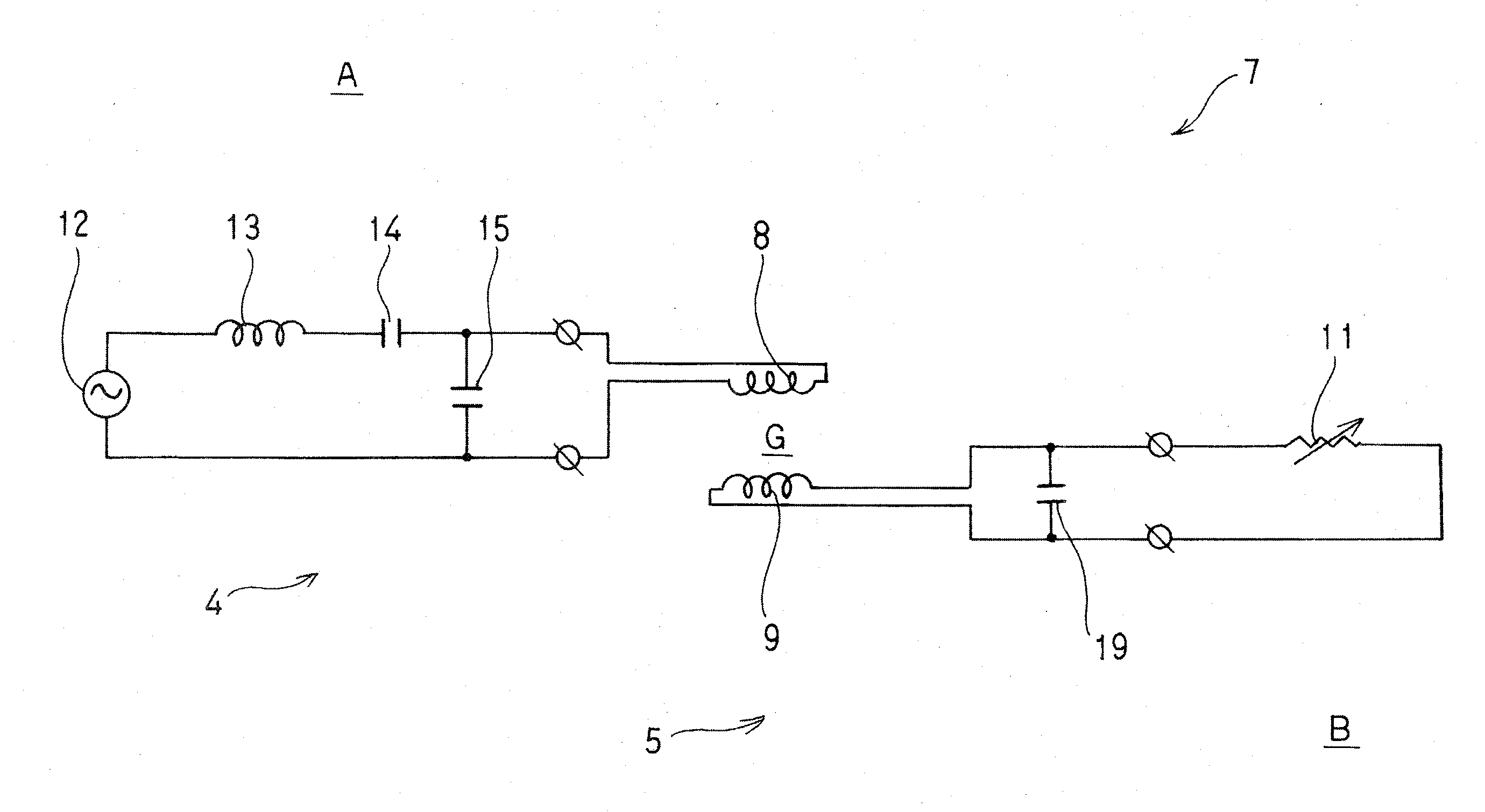
[0065]The non-contact power feeding apparatus 7 is provided in such a manner that electric power is fed through an air gap G, with no contact, from a power transmission coil 8 of a power feeding side circuit 4 to a power receiving coil 9 of a power receiving side circuit 5, which are closely located to face each other, based on a mutual induction effect of the electromagnetic induction. The power feeding side circuit 4 is fixedly disposed on the side of the ground A, while the power receiving side circuit 5 is mounted on the side of a movable body such as a vehicle B.

[0066]Such a non-contact power feeding apparatus 7 will be further described. First, the power feeding side circuit 4 ...


PUM


Abstract

In a non-contact power feeding apparatus of the present invention, power is fed through an air gap from a power transmission coil of a power feeding side circuit to a power receiving coil of a power receiving side circuit, which are closely located to face each other, based on a mutual induction effect of electromagnetic induction. The power transmission coil and the power receiving coil are respectively composed of a planar assembly of a number of unit coils. Each unit coil is formed in a spirally wound flat structure, wherein the direction of an electric current is set in reverse to make the north and south magnetic poles reverse between each unit coil which is juxtaposed to another to directly come into line. As a result, the unit coils, which are juxtaposed to another to directly come into line, are provided in such a manner that an overlapping area of a respectively formed magnetic field cancels another out to be offset

Description

BACKGROUND OF THE INVENTION[0001]The present invention relates to a non-contact power feeding apparatus, and more particularly to a non-contact power feeding apparatus adapted to feed power with no contact from, for example, a power feeding side of a ground surface side to a power receiving side of a vehicle side.[0002]A non-contact power feeding apparatus adapted to feed power from outside to, for example, a vehicle such as an electric vehicle without any mechanical contact such as a cable has been developed based on the demand and this apparatus is in practical use.[0003]In such a non-contact power feeding apparatus, power is fed through an air gap of, for example, tens of millimeters to hundreds of millimeters from a power transmission coil of a power feeding side circuit fixedly disposed on the ground side to a power receiving coil of a power receiving side circuit mounted on the side of a movable body such as a vehicle, based on a mutual induction effect of electromagnetic indu...

Claims


Application Information

Patent Timeline
IPC IPC(8): H01F38/14B60L5/00B60M7/00
CPCH02J5/005H02J50/402H02J50/12H02J50/10H02J50/70
Inventor YAMAMOTO, KITAOSATO, TAKESHIABE, KEISUKEMOCHIZUKI, MASASHIOKIYONEDA, YASUYUKI
Owner SHOWA AIRCRAFT INDUSTRY
Learn More