Rotor for automotive alternator

Inactive Publication Date: 2014-06-26
DENSO CORP
View PDF7 Cites 4 Cited by
  • Summary
  • Abstract
  • Description
  • Claims
  • Application Information

AI Technical Summary

Benefits of technology

The patent describes a configuration for an alternator that reduces leakage magnetic flux and prevents a decrease in effective magnetic flux, resulting in a higher output. This can be achieved by increasing air gaps between the magnetic pole claws and the teeth of the stator core. Additionally, increasing the axial length of the stator core allows for more steel sheets, resulting in more output without increasing manufacturing costs.

Problems solved by technology

Consequently, when the radial distance is increased for reducing the leakage magnetic flux at those areas of the chamfered portion which are close to the boundary line, the radial distance may become excessively long at those areas of the chamfered portion which are distant from the boundary line, thereby reducing the effective magnetic flux.
As a result, it may be difficult to achieve the desired effect of increasing the output of the alternator by reducing the leakage magnetic flux.
Moreover, with the above-described configuration of the chamfered portions, there still remains the problem that the chamfered portions function as a fan to generate wind noise during rotation of the rotor.
In addition, it may be difficult to minimize the manufacturing cost of the alternator.

Method used


Image

  • Rotor for automotive alternator
  • Rotor for automotive alternator
  • Rotor for automotive alternator

Examples


Embodiment Construction

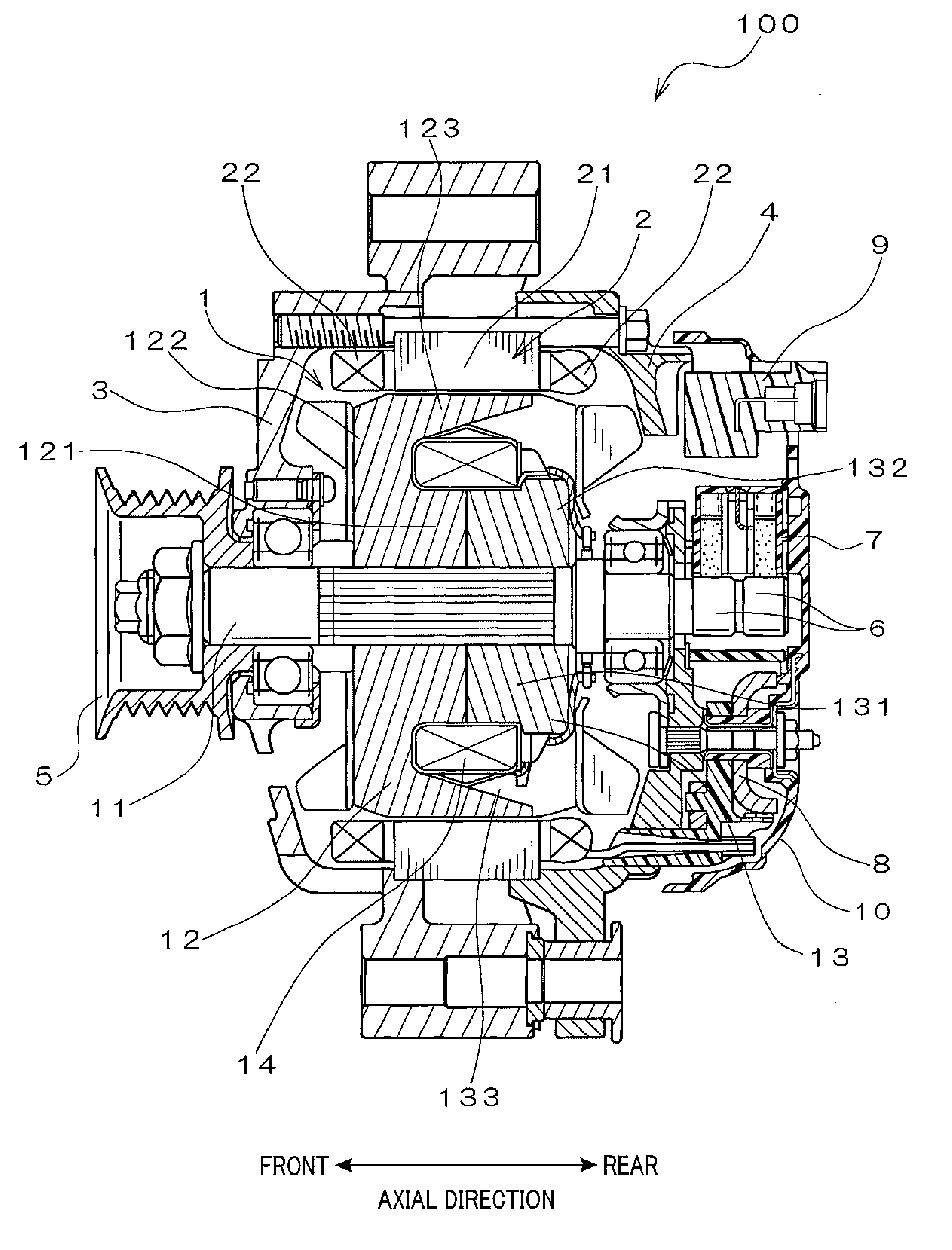
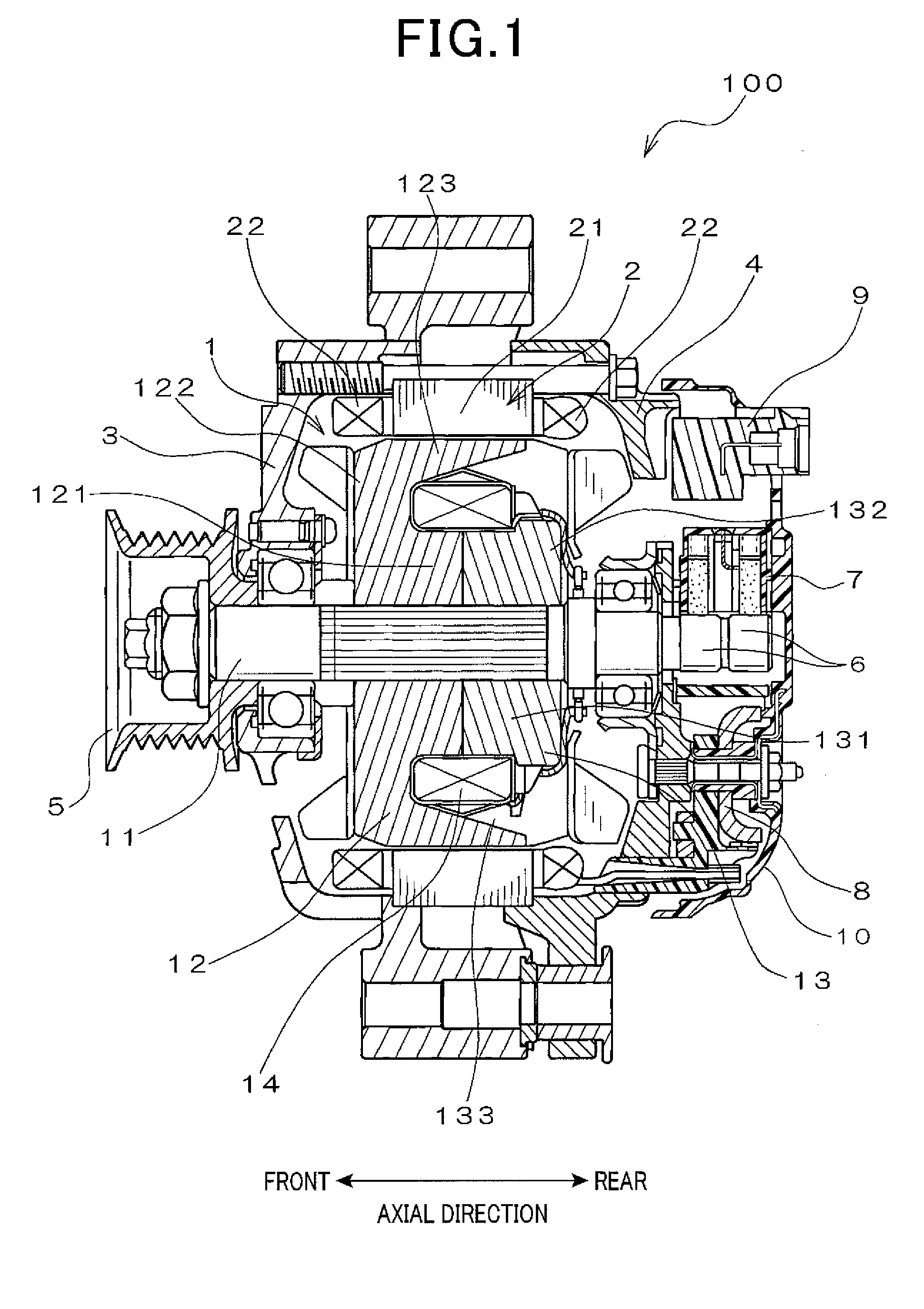
[0033]FIG. 1 shows the overall configuration of an automotive alternator 100 which includes a rotor 1 according to an exemplary embodiment. The alternator 100 is designed to be used in a motor vehicle, such as a passenger car or a truck.

[0034]As shown in FIG. 1, the alternator 100 includes, in addition to the rotor 1, a stator 2, a front housing 3, a rear housing 4, a pulley 5, a pair of slip rings 6, a brush assembly 7, a rectifier 8, a voltage regulator 9, and a rear cover 10.

[0035]The stator 2 is arranged radially outside of the rotor 1. More specifically, the stator 2 includes an annular stator core 21 that is disposed so as to surround the rotor 1 and a three-phase stator coil 22 wound around the stator core 21.

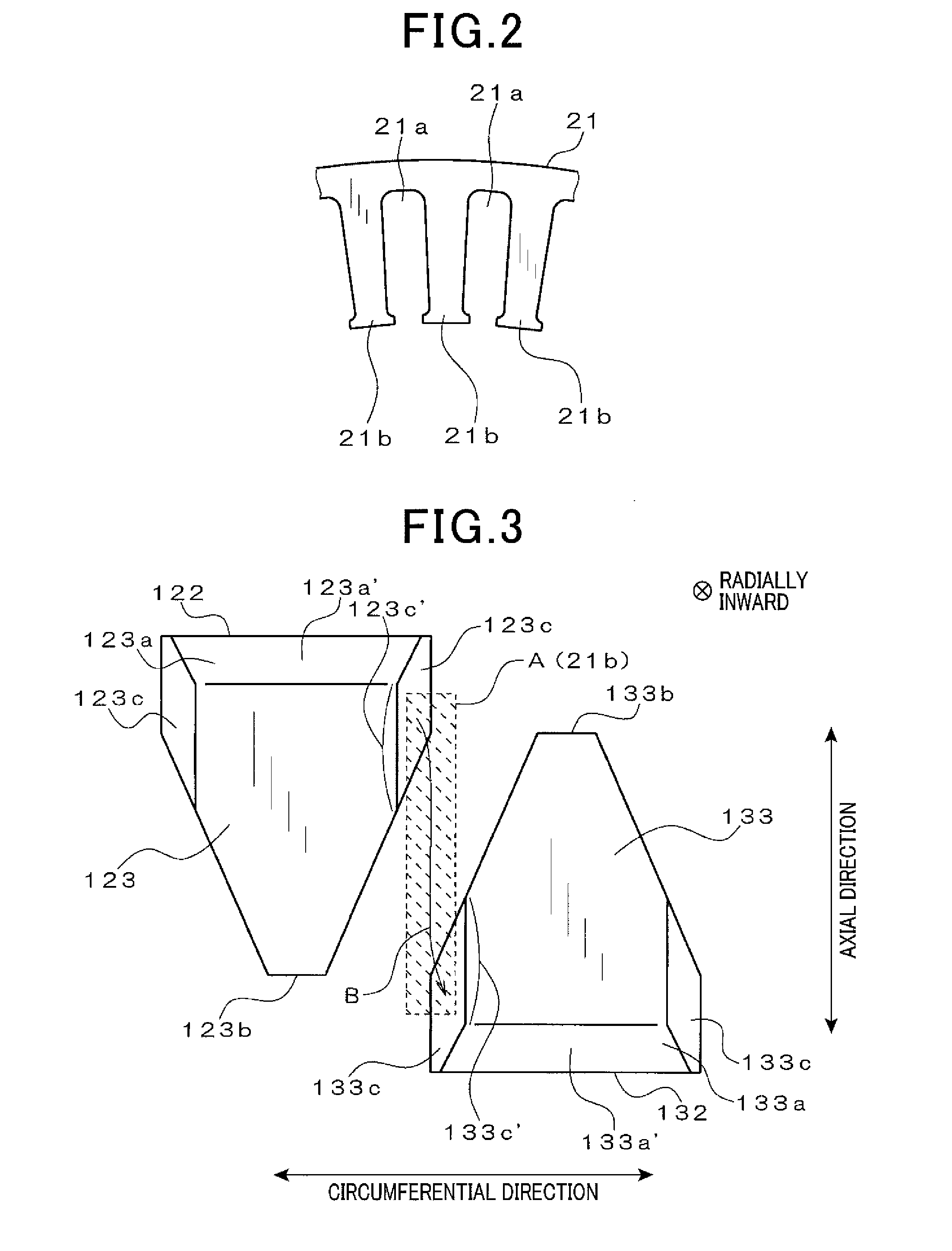
[0036]Moreover, as shown in FIG. 2, the stator core 21 has a plurality of slots 21a formed therein. The slots 21a are spaced from one another in the circumferential direction of the stator core 21 at predetermined intervals and open at the radially inner periphery of the...


PUM


Abstract

A rotor includes a rotating shaft and a pair of first and second pole cores fixed on the rotating shaft. Each of the first and second pole cores includes a plurality of magnetic pole claws each having a root portion and a distal end. Each of the magnetic pole claws are configured to have a constant circumferential width at the root portion and taper from the root portion to the distal end. The magnetic pole claws of the first pole core are arranged alternately with those of the second pole core in a circumferential direction of the rotating shaft. Further, at least part of the magnetic pole claws of the first and second pole cores each have at least one chamfered portion formed at a circumferential end of the root portion of the magnetic pole claw so as to extend parallel to an axial direction of the rotating shaft.

Description

CROSS-REFERENCE TO RELATED APPLICATION[0001]This application is based on and claims priority from Japanese Patent Application No. 2012-280432, filed on Dec. 25, 2012, the content of which is hereby incorporated by reference in its entirety into this application.BACKGROUND OF THE INVENTION[0002]1. Technical Field of the Invention[0003]The present invention relates to rotors for automotive alternators that are used in, for example, passenger cars and trucks.[0004]2. Description of the Related Art[0005]Japanese Unexamined Patent Application Publication No. 2002-354720, an English equivalent of which is U.S. Pat. No. 6,476,535 B1, discloses an automotive alternator. This alternator is designed to increase an output of the alternator by reducing leakage magnetic flux that flows between adjacent magnetic pole claws of a rotor via teeth of a stator core when the magnetic pole claws are at a predetermined relative position to the teeth of the stator core in the alternator.[0006]Specifically...

Claims


Application Information

Patent Timeline
IPC IPC(8): H02K1/24
CPCH02K1/243
Inventor SEKIYAMA, YOSUKEASANO, NOBUHIRO
Owner DENSO CORP
Why Eureka
Try Eureka