Coil component

Active Publication Date: 2017-11-16
TDK CORPARATION
View PDF3 Cites 3 Cited by
  • Summary
  • Abstract
  • Description
  • Claims
  • Application Information

AI Technical Summary

Benefits of technology

The present invention provides a coil component that can be mounted high density on a printed circuit board with reduced leakage magnetic flux and suppression of eddy current loss and magnetic saturation. This is achieved by dividing the magnetic film on the upper surface into multiple parts to reduce eddy current and saturation. The magnetic film also covers the side surface of the element body to suppress magnetic flux spreading and higher mounting density is achievable. The invention also includes a configuration where each magnetic film is separated by slits to reduce eddy current loss and magnetic saturation. Overall, the invention enables high-density mounting with reduced leakage magnetic flux, suppressed eddy current loss and magnetic saturation, and reduced adverse effects on adjacent electronic components.

Problems solved by technology

However, a part of the magnetic flux leaks outside the element body, which may degrade magnetic characteristics or may adversely affect other electronic components adjacent to the coil component.
However, in the coil component described in the above publications, a large eddy current is generated in the magnetic film with a change in the magnetic flux, resulting in a large eddy current loss.
Furthermore, in this coil component, spread of the magnetic flux in the side surface direction of the coil component is not sufficiently suppressed, so that when the coil component is mounted on a printed circuit board in a high density, other electronic components adjacent thereto may be affected by leakage magnetic flux.
This configuration makes the magnetic film more difficult to magnetically saturate, reducing an eddy current loss.

Method used


Image

  • Coil component
  • Coil component
  • Coil component

Examples


first embodiment

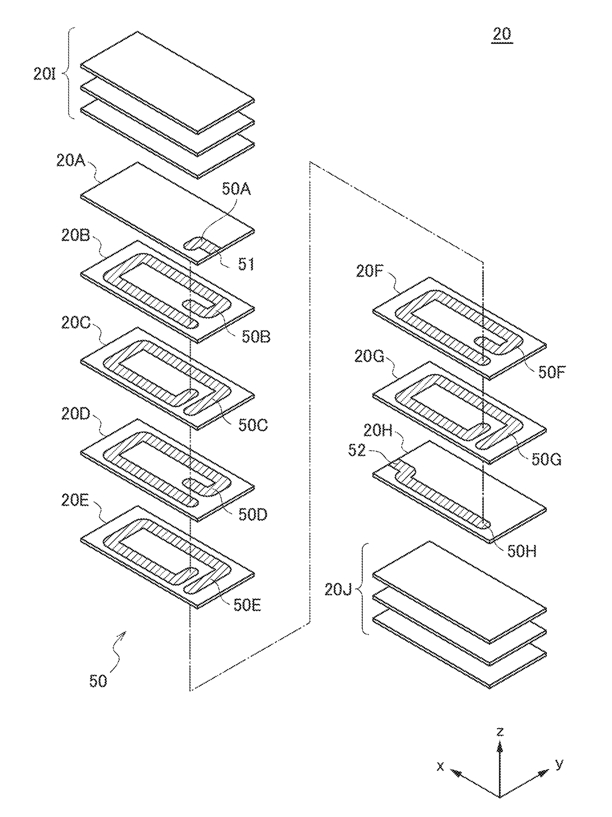
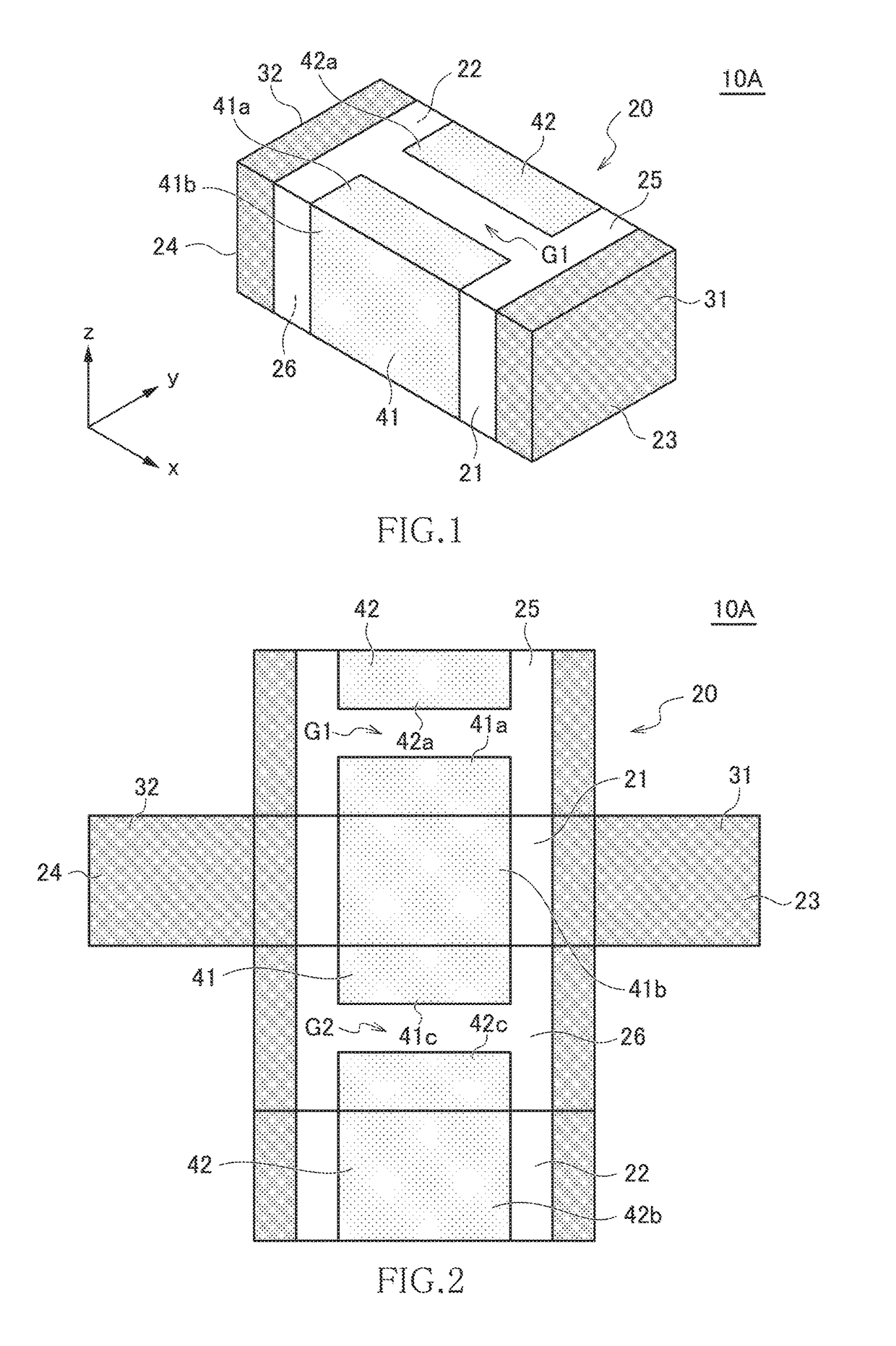
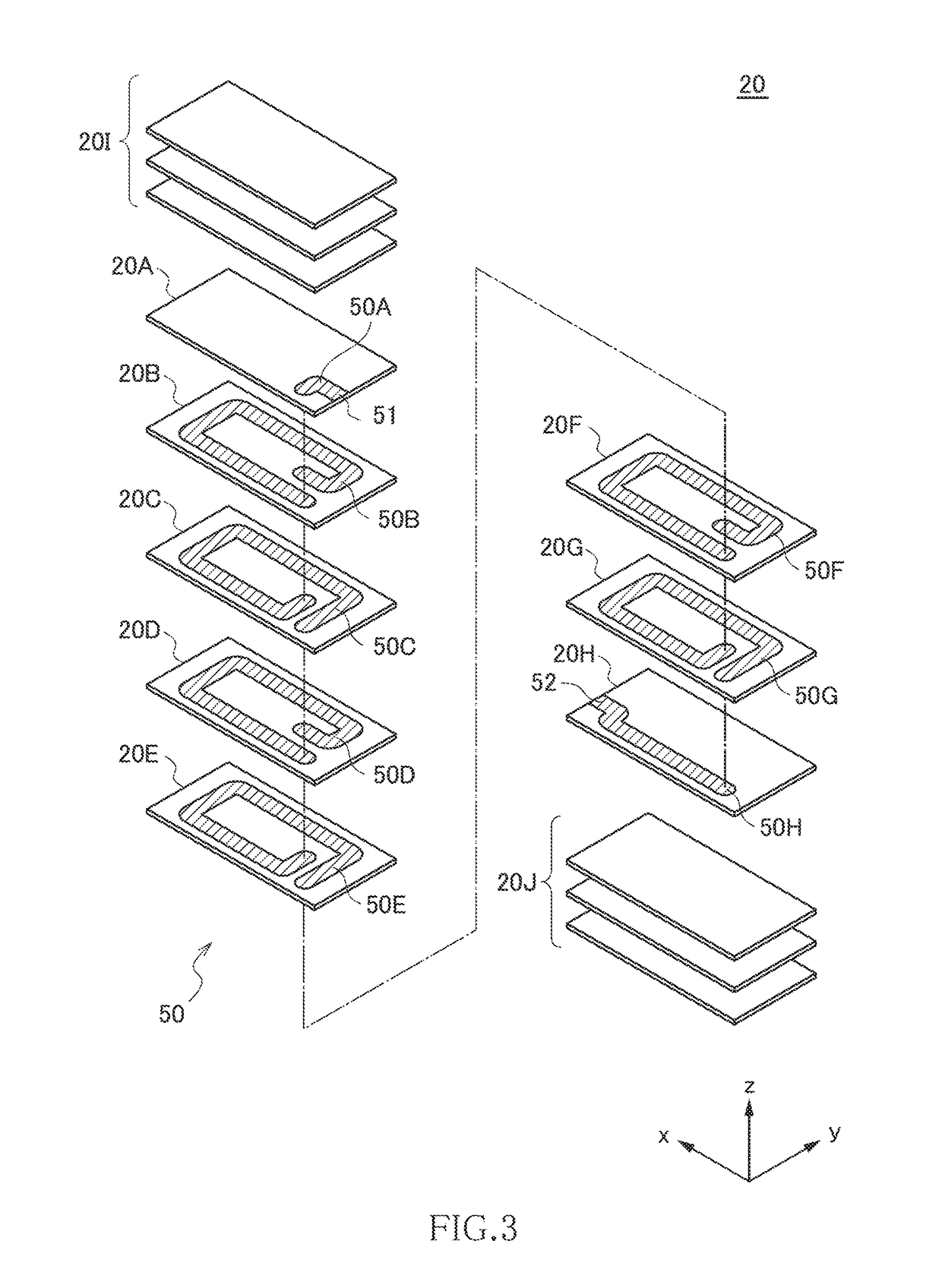
[0024]FIG. 1 is a schematic perspective view illustrating the outer appearance of a coil component 10A according to the first embodiment of the present invention. FIG. 2 is a development view for explaining the surface structure of the coil component 10A. FIG. 3 is an exploded perspective view for explaining the internal structure of the coil component 10A.

[0025]As illustrated in FIGS. 1 and 2, the coil component 10A according to the present embodiment includes an element body 20 having a substantially rectangular parallelepiped shape, first and second terminal electrodes 31 and 32 formed on the surface of the element body 20, and first and second magnetic films 41 and 42 formed on the surface of the element body 20. Although not particularly limited, the coil component 10A according to the present embodiment is suitably used as a power supply inductor, in which a larger current than that in a coil component used as a signal inductor flows, so that a large number of magnetic fluxes ...

second embodiment

[0038]FIG. 4 is a schematic perspective view illustrating the outer appearance of a coil component 10B according to the second embodiment of the present invention. FIG. 5 is a development view for explaining the surface structure of the coil component 10B.

[0039]As illustrated in FIGS. 4 and 5, the coil component 10B according to the present embodiment differs from the coil component 10A according to the first embodiment in that slits G3 and G4 are formed in the first and second magnetic films 41 and 42, respectively. Other configurations are the same as those of the coil component 10A according to the first embodiment, so the same reference numerals are given to the same elements, and overlapping description will be omitted.

[0040]The slit G3 is formed in the part 41b of the first magnetic film 41 that covers the first side surface 21 and extends in the x-direction so as to separate the part 41b in the z-direction. Similarly, the slit G4 is formed in the part 42b of the second magnet...

third embodiment

[0042]FIG. 6 is a schematic perspective view illustrating the outer appearance of a coil component 10C according to the third embodiment of the present invention. FIG. 7 is a development view for explaining the surface structure of the coil component 10C.

[0043]As illustrated in FIGS. 6 and 7, the coil component 10C according to the present embodiment differs from the coil component 10A according to the first embodiment in that third and fourth magnetic films 43 and 44 are additionally formed. Other configurations are the same as those of the coil component 10A according to the first embodiment, so the same reference numerals are given to the same elements, and overlapping description will be omitted.

[0044]The third magnetic film 43 is formed on the upper surface 25 of the element body 20 independent of the first and second magnetic films 41 and 42. Similarly, the fourth magnetic film 44 is formed on the mounting surface 26 of the element body 20 independent of the first and second m...


PUM


Abstract

Disclosed herein is a coil component that includes an element body made of a first magnetic material, a coil conductor embedded in the element body, and first and second magnetic films made of a second magnetic material having higher permeability than that of the first magnetic material. The element body has an upper surface crossing a coil axis of the coil conductor and first and second side surfaces extending substantially parallel to the coil axis. The first magnetic film is formed on the upper surface and first side surface of the element body, and the second magnetic film is formed on the upper surface and second side surface of the element body.

Description

BACKGROUND OF THE INVENTIONField of the Invention[0001]The present invention relates to a coil component and, more particularly, to a coil component obtained by embedding a coil conductor in an element body made of a magnetic material.Description of Related Art[0002]There is widely known a coil component obtained by embedding a coil conductor in an element body made of a magnetic material. In a coil component of this type, an element body is made of a magnetic material, so that most of the magnetic flux generated by making current flow in a coil conductor can be confined inside the element body. However, a part of the magnetic flux leaks outside the element body, which may degrade magnetic characteristics or may adversely affect other electronic components adjacent to the coil component.[0003]To cope with such a problem, Japanese Patent Application Laid-open No. 2013-045848 and Japanese Utility Model Application Laid-open No. H02-067609 disclose a coil component in which a magnetic ...

Claims


Application Information

Patent Timeline
IPC IPC(8): H01F17/00H01F27/29H01F10/26H01F5/00H01F27/28
CPCH01F17/0013H01F27/292H01F5/003H01F10/26H01F2017/0066H01F2017/0053H01F2017/0073H01F2027/2809H01F17/04H01F2003/106H01F2017/008H01F27/36H01F27/366
Inventor TOMONARI, TOSHIOTAKANO, SACHIKOSATO, SHIGEKI
Owner TDK CORPARATION
Why Eureka
Try Eureka