Surface installation inductor

A surface mount type, inductor technology, applied in the direction of transformer/inductor core, transformer/inductor coil/winding/connection, etc., can solve the problems of equipment influence, leakage magnetic flux, etc., to improve inductance value and position accuracy , Workability improvement effect

Inactive Publication Date: 2007-04-04
TOKYO PARTS IND CO LTD
View PDF1 Cites 18 Cited by
  • Summary
  • Abstract
  • Description
  • Claims
  • Application Information

AI Technical Summary

Problems solved by technology

However, if the T-shaped core is viewed from above, leakage magnetic flux will be generated from the gap and affect surrounding equipment

Method used


Image

  • Surface installation inductor
  • Surface installation inductor
  • Surface installation inductor

Examples


no. 1 Embodiment approach

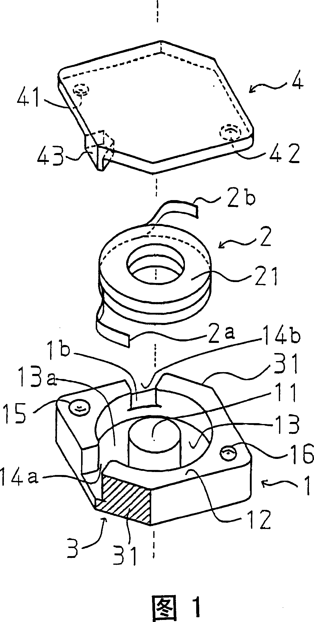
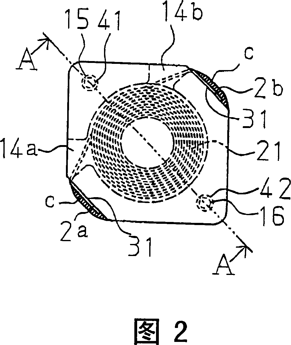
[0036] As shown in FIGS. 1 to 4 , the surface-mounted inductor of this embodiment is composed of the following parts: a cylindrical core 1 whose bottom surface is approximately square, and has a cylindrical magnetic core part 11 and an outer wall 12 in the center; The coil 2 is fitted on the magnetic core part 11 of the cylindrical core 1; the electrode 3 is arranged on the outer peripheral surface of the cylindrical core 1 and is electrically connected with the flat coil 2; The barrel core 1 is closed.

[0037] The cylindrical core 1 is made of a ferrite material, and has a substantially square bottom surface, a columnar core portion 11 at the center, and an outer wall 12 integrally erected with the bottom surface. Between the core part 11 and the outer wall 12, a coil housing part 13 for housing the flat coil 2 is provided. Moreover, the coil housing part 13 has the bottom surface part 13a which arrange|positions the bottom surface of the flat coil 2 wound.

[0038] In add...

no. 2 Embodiment approach

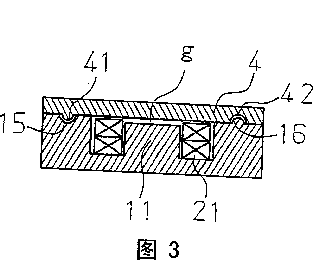
[0056] In the surface mount inductor of this embodiment, as shown in FIG. 5 , a magnetic core part is also provided on the cover core 4, and the height of the magnetic core part 11 of the cylindrical core 1 is made low so that it is in contact with the cover core. The magnetic core portion of 4 has a predetermined air gap g, and other configurations are the same as those of the first embodiment.

[0057] Alternatively, the magnetic core portion may be provided only on the cover core so that a predetermined air gap g is provided between the magnetic core portion and the bottom portion of the cylindrical core.

[0058] Owing to be the structure as above, so, as the effect of the present invention, owing to be provided with the cylindrical core 1 that has outer wall and the cap core 4 that closes the open end of this cylindrical core 1, so between the outer wall of this cylindrical core 1 and There is no gap between the cover cores 4, and when the cylindrical core 1 is viewed fro...


PUM


Abstract

The present invention provides a surface-mounting inductor resolving the requirement for downsizing and a low profile having good assembling workability, an improved electrical characteristic, and no leakage magnetic flux. The surface-mounting inductor comprises a pot-type core having an external wall, a rectangular coil fixed to the pot-type core, a pair of electrodes provided on an outer periphery surface of the pot-type core, and a cover core for closing an opening end of the pot-type core. The pot-type core comprises a positioning mechanism for positioning with the cover core at the opening end, and two U shape windows having an open space adjacently over the electrode. The height of the bottom face of one U shape window is higher than that of the other U shape window by the width of a rectangular wire, and a protruding portion (43) having a height corresponding to the wire width of the rectangular coil is provided to the part of the cover core (4) corresponding to the other window (14a).

Description

technical field [0001] The present invention relates to a surface mount inductor in which a cylindrical core and a cover core are laminated from top to bottom and accommodates a flat coil. In particular, it relates to a surface mount inductor capable of improving assembly accuracy, improving inductance characteristics, and eliminating leakage magnetic flux. Background technique [0002] Patent Document 1 is known as a prior art document related to the present application, for example. [0003] Patent Document 1 Japanese Patent Laid-Open No. 2004-207371 [0004] The surface mount inductor of Document 1 will be described below with reference to the drawings. [0005] FIG. 6 is a perspective view of the surface mount inductor of Document 1. FIG. [0006] In FIG. 6, Document 1 is composed of a core 100 made of ferrite, having a rectangular bottom portion, a pair of peripheral wall portions protruding upward are erected at both ends of the bottom portion, and A cylindrical mag...

Claims


Application Information

Patent Timeline
Patent Type & Authority Applications(China)
IPC IPC(8): H01F27/24H01F27/28
Inventor 水谷升
Owner TOKYO PARTS IND CO LTD
Why Eureka
Try Eureka