Semiconductor device and method for its manufacture

Inactive Publication Date: 2010-09-23
ROBERT BOSCH GMBH
View PDF3 Cites 12 Cited by
  • Summary
  • Abstract
  • Description
  • Claims
  • Application Information

AI Technical Summary

Benefits of technology

[0014]The core of the present invention is formed by Schottky diodes having high robustness and a small forward voltage, suitable for use

Problems solved by technology

The main disadvantage is the high forward voltage UF.
Under normal operating conditions, e.g. a current density of 500 A/cm2, UF increases to greater than 1V, resulting in a non-negligible loss of efficiency.
However, up to now Schottky diodes have not been used in vehicle generator systems.
This is due to some decisive disadvantages of Schottky diodes: 1)

Method used


Image

  • Semiconductor device and method for its manufacture
  • Semiconductor device and method for its manufacture
  • Semiconductor device and method for its manufacture

Examples


Embodiment Construction

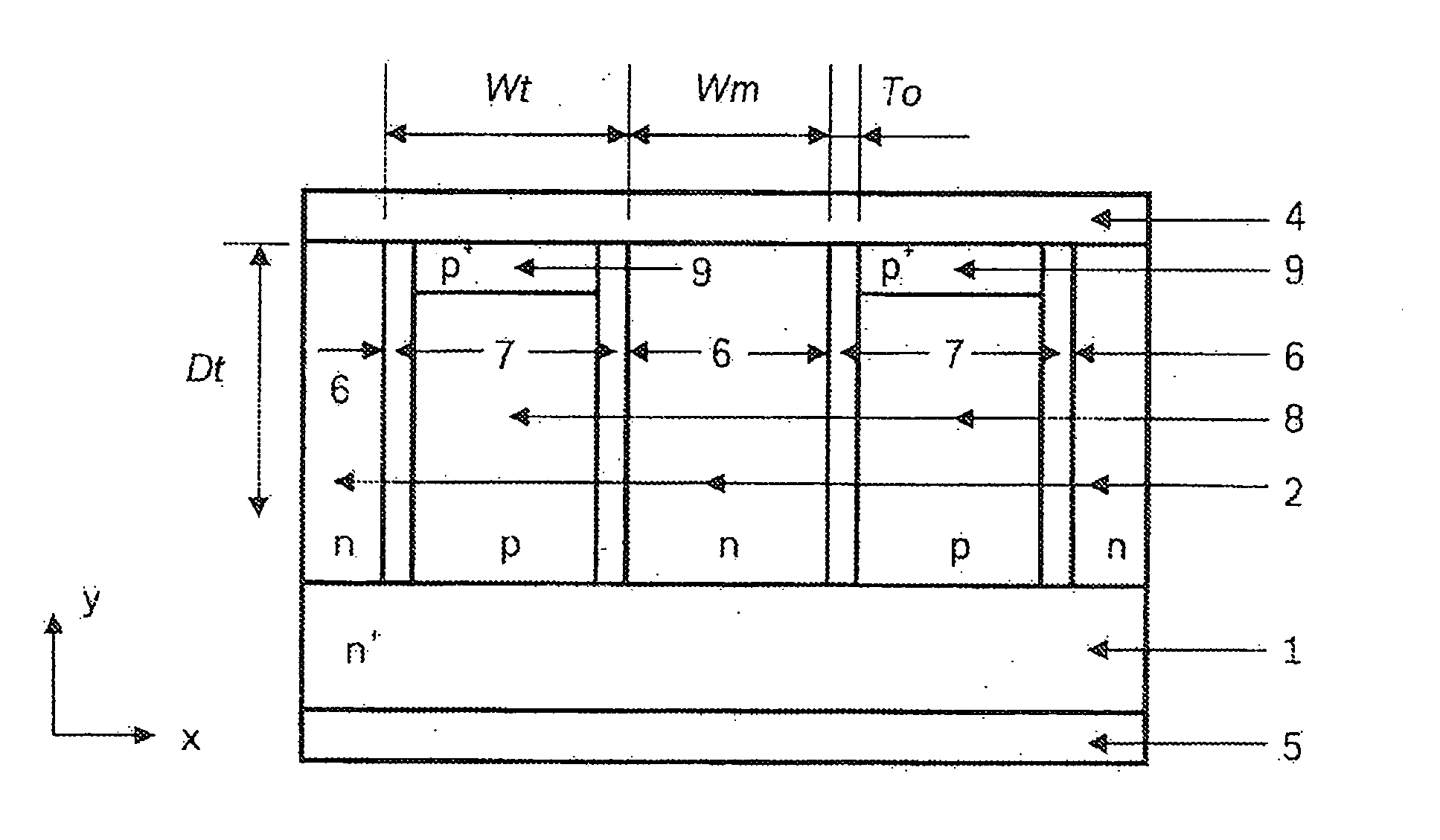
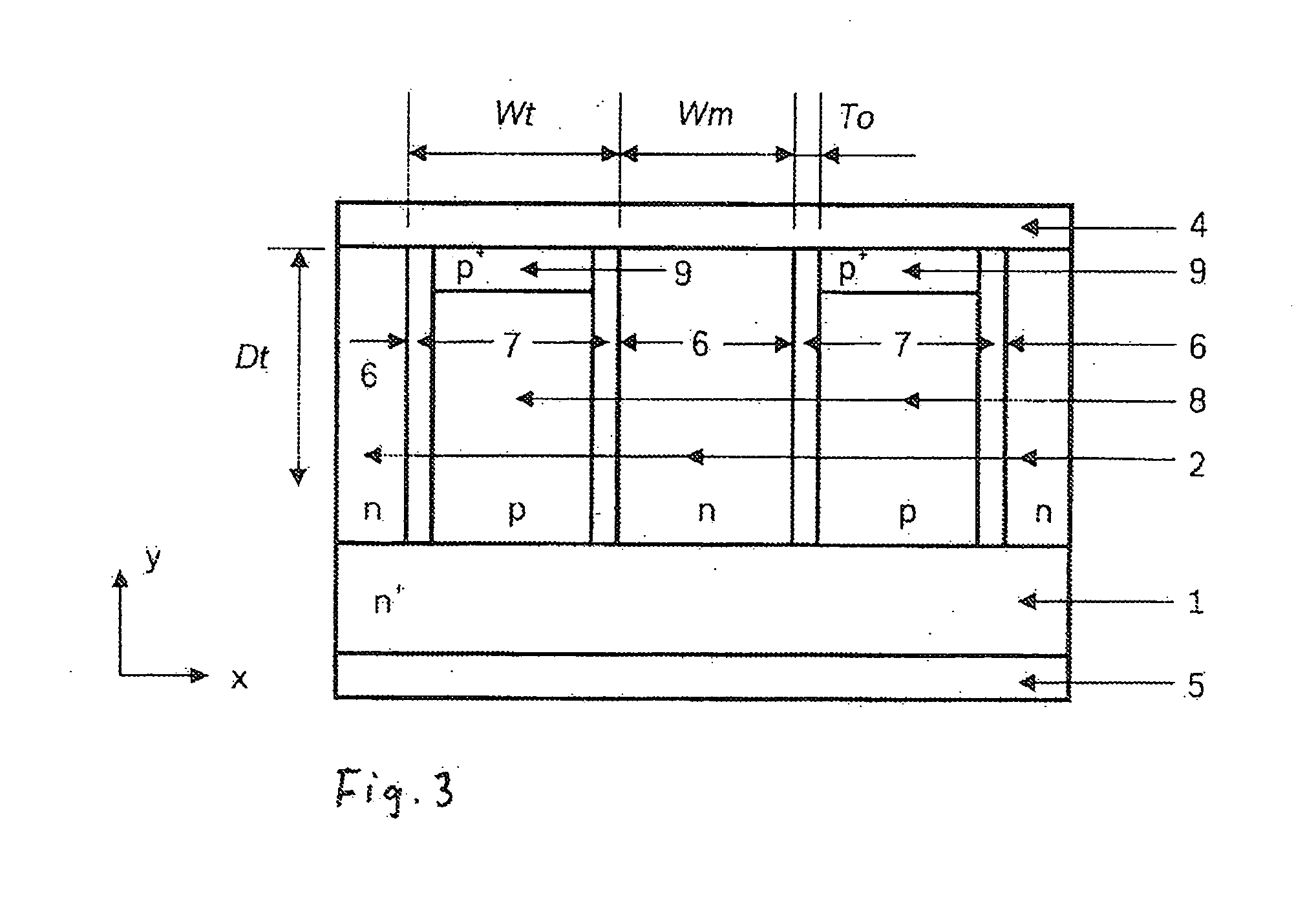
[0022]As FIG. 3 shows, the TMBS-sub-PN according to the present invention is made up of an n+ substrate 1, an n-epitaxial layer 2, at least two trenches 6 etched through n-epitaxial layer 2 down to n+ substrate 1, said trenches having a width Wt, a depth Dt, and a distance Wm between adjacent trenches 6, metallic layers on the, front side of chip 4 as anode electrode and on the rear side of chip 5 as cathode electrode, and oxide layers 7 having a thickness To on the side walls of trenches 6. The regions between oxide layers 7 in trenches 8 are filled with p-doped Si or poly-Si, and in their upper regions there are situated additional thin p+ layers 9 for ohmic contact with metallic layer 4.

[0023]Regarded electrically, the TMBS-sub-PN is a combination of an MOS structure, i.e. a metallic layer 4 in combination with p-tub 8, oxide layer 7, and n-epitaxial layer 2, a Schottky diode having a Schottky barrier between metallic layer 4 as anode and n-epitaxial layer 2 as cathode, and a sub...


PUM


Abstract

A semiconductor system having a trench MOS barrier Schottky diode, having an integrated substrate PN diode as a clamping element (TMBS-ub-PN), suitable in particular as a Zener diode having a breakdown voltage of approximately 20V for use in a vehicle generator system, the TMBS-sub-PN being made up of a combination of Schottky diode, MOS structure, and substrate PN diode, and the breakdown voltage of substrate PN diode BV_pn being lower than the breakdown voltage of Schottky diode BV_schottky and the breakdown voltage of MOS structure BV_mos.

Description

BACKGROUND OF THE INVENTION[0001]1. Field of the Invention[0002]The present invention relates to a Trench MOS Barrier Schottky Diode having an integrated Substrate-PN diode as a clamping element, hereinafter referred to as a TMBS-sub-PN, suitable for use as a Zener power diode having a breakdown voltage of approximately 20 V for use in vehicle generator systems.[0003]2. Description of Related Art[0004]In modern motor vehicles, functions are increasingly realized using electronic components. This creates a growing need for electrical power. In order to meet this need, the efficiency of the vehicle generator system has to be increased. Standardly, as a rule PN diodes are used as Zener diodes in the vehicle generator system. Advantages of the PN diodes are on the one hand their low blocking voltage and on the other hand high robustness. The main disadvantage is the high forward voltage UF. At room temperature, current does not begin to flow until UF=0.7V. Under normal operating conditi...

Claims


Application Information

Patent Timeline
IPC IPC(8): H01L29/866
CPCH01L29/0619H01L29/0634H01L29/8725H01L29/872H01L29/0649
Inventor QU, NINGGOERLACH, ALFRED
Owner ROBERT BOSCH GMBH
Why Eureka
Try Eureka