Transferring electric energy to a vehicle

a technology of electric energy and electric power, which is applied in the direction of propulsion by capacitors, rail devices, transportation and packaging, etc., can solve the problems of large storage capacity of energy storage on board the vehicle, undesirable overhead lines, safety problems, etc., and achieve the reduction of reactive power of the system, the reduction of leakage inductance, and the reduction of the design of the active power components.

Active Publication Date: 2013-11-26
BOMBARDIER TRANSPORTATION GMBH
View PDF154 Cites 11 Cited by
  • Summary
  • Abstract
  • Description
  • Claims
  • Application Information

AI Technical Summary

Benefits of technology

[0045]In a preferred embodiment, the lines of the multi-phase conductor arrangement are connected at a star point, i.e. the lines are connected to each other at a connection point which is common to all phases. Such a star point configuration is particularly easy to realize and ensures that the behaviour of the plural phases is symmetric, i.e. that all phases carry the same effective current, although—of course—there is a phase shift between the phases. For example in the case of a three-phase system, the phase shift is 120°, as usual. The alternating current in each phase may be a sinusoidal or nearly sinusoidal current. An additional advantage of a star point connection is that no backward conductor to the power

Problems solved by technology

However, especially in historic parts of cities, overhead lines are undesirable.
On the other hand, conductor rails in the ground or near the ground cause safety problems.
Placing the coils at selected locations along the length of the roadway has the disadvantage that the ener

Method used


Image

  • Transferring electric energy to a vehicle
  • Transferring electric energy to a vehicle
  • Transferring electric energy to a vehicle

Examples


Embodiment Construction

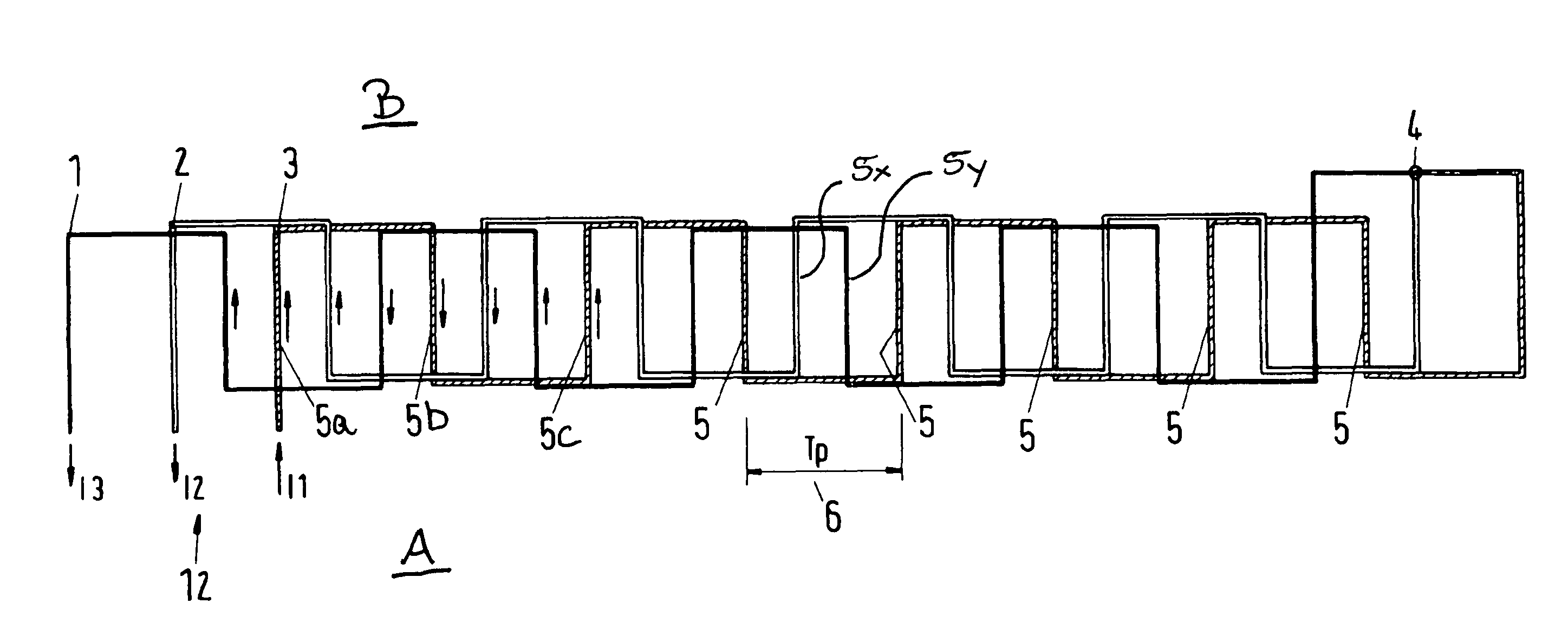
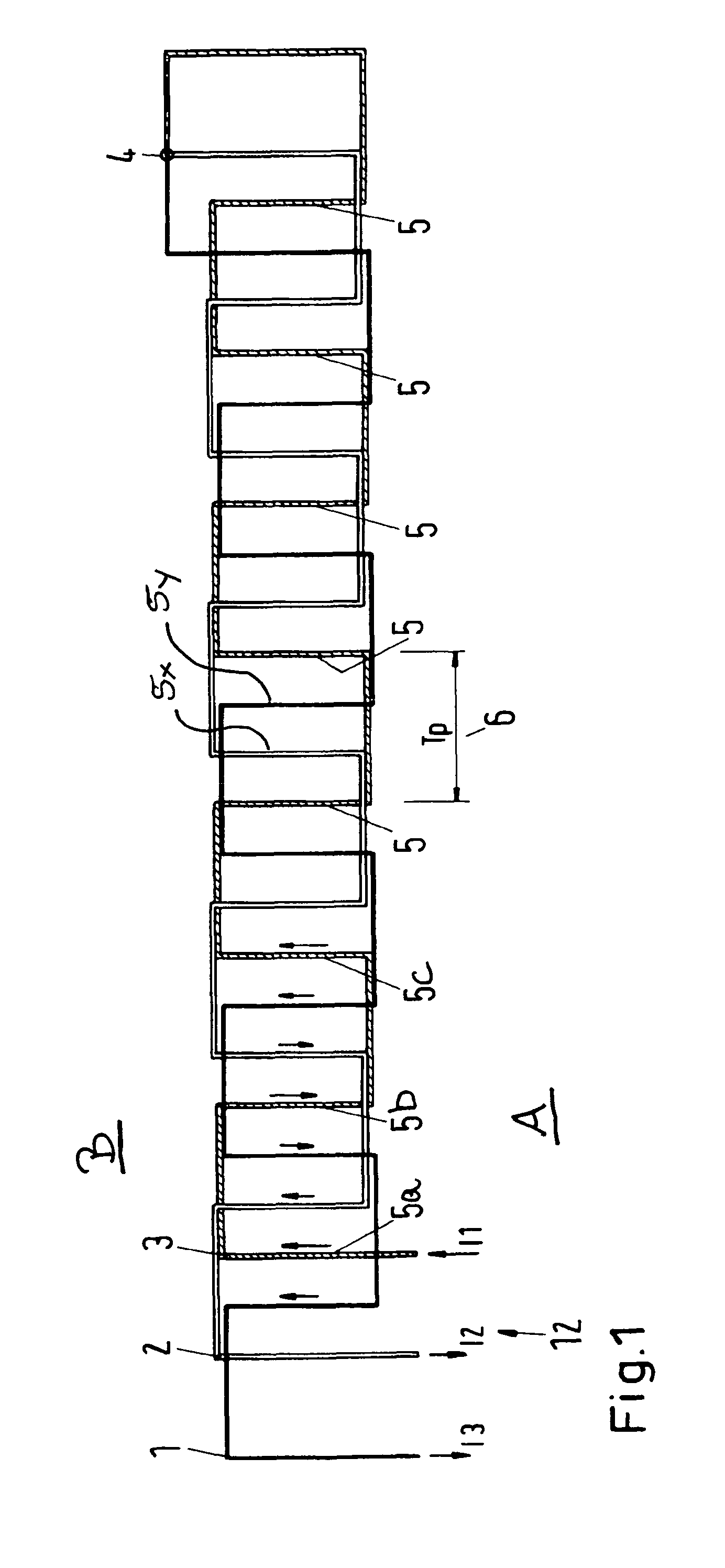
[0071]FIG. 1 shows a conductor arrangement which may be located underground along a track, for example along the rails of a railway (see the arrangement shown in FIG. 11, for example). In the latter case, the rails extend from left to right in the view of FIG. 1.

[0072]FIG. 1 is understood to be a schematic view. The three lines 1, 2, 3 of the conductor arrangement comprise sections which extend transversely to the direction of travel (from left to right or right to left). Only some of the transversely extending sections of lines 1, 2, 3 are denoted by the reference numerals, namely three sections 5a, 5b and 5c of line 3, some further sections of the line 3 by “5”, one section 5x of line 2 and one section 5y of line 1. In the most preferred case, the arrangement 12 shown in FIG. 1 is located underground of the track so that FIG. 1 shows a top view onto the arrangement 12. The rails may extend from left to right, at the top and the bottom in FIG. 1, i.e. the transversely extending lin...


PUM


Abstract

The invention relates to a system for transferring electric energy to a track bound vehicle, in particular to a light rail vehicle, such as a tram, wherein the system comprises an electric conductor arrangement (12) for producing an electromagnetic field and for thereby transferring the energy to the vehicle, the electric conductor arrangement (12) comprises at least one line (1, 2, 3) for carrying one phase of an alternating voltage or current, the line (1, 2, 3) extends along the track, the line (1, 2, 3) is arranged in such a manner that it produces—at each point in time while the alternating electric current is flowing through the line (1, 2, 3)—a row of successive magnetic poles (at sections 5) of an electromagnetic field, wherein the successive magnetic poles have alternating magnetic polarities, the row of successive magnetic poles extends in the travel direction of the vehicle which is defined by the track.

Description

BACKGROUND OF THE INVENTION[0001]1. Field of the Invention[0002]The invention relates to a system and a method for transferring electric energy to a vehicle, in particular to a track bound vehicle such as a light rail vehicle (e.g. a tram).[0003]2. Description of the Related Art[0004]In particular track bound vehicles, such as conventional rail vehicles, mono-rail vehicles, trolley busses and vehicles which are guided on a track by other means, such as other mechanical means, magnetic means, electronic means and / or optical means, require electric energy for propulsion on the track and for operating auxiliary systems, which do not produce traction of the vehicle. Such auxiliary systems are, for example, lighting systems, heating and / or air condition system, the air ventilation and passenger information systems. However, more particularly speaking, the present invention is related to transferring electric energy to a vehicle which is not necessarily (but preferably) a track bound vehi...

Claims


Application Information

Patent Timeline
IPC IPC(8): B60L9/00
CPCB60L5/005B60L11/005B60L2210/20B60L2210/30Y02T10/725Y02T10/7241Y02T10/7022B60L2200/26B60L50/40Y02T10/72H02M7/05Y02T10/7072Y02T10/70Y02T90/14B60L9/00B60L9/16B60L5/00B60M7/00H02J50/10B60M7/003
Inventor MEINS, JURGENSTRUVE, CARSTEN
Owner BOMBARDIER TRANSPORTATION GMBH
Why Eureka
Try Eureka