Method for displaying position of an aircraft in a display for air traffic control

a technology of air traffic control and aircraft position, which is applied in the direction of navigation instruments, using reradiation, instruments, etc., can solve the problems of inability to comprehensively and visually grasp relative relationships, inability to accurately identify aircraft positions, and inability to accurately display aircraft positions, so as to ensure the safety distance between aircraft and effectively avoid the occurrence of near collisions.

Inactive Publication Date: 2005-02-17
REALVIZ +1
View PDF4 Cites 38 Cited by
  • Summary
  • Abstract
  • Description
  • Claims
  • Application Information

AI Technical Summary

Benefits of technology

[0011] It is a first object of the present invention to provide a method for displaying aircraft positions, which is capable of displaying relative relationships between aircraft under air traffic control, including the distances between two aircraft, and their changing status in the distances between aircraft, apparently in three dimensions (3D) on a display screen of a display system to comprehensively and visually grasp the relative relationships, which is capable of performing adequate surveillance by promptly predicting whether the near miss or collision between aircraft would occur, and which is capable of ensuring a safety distance between aircraft by sending a necessary control command in order to effectively avoid the occurrence of near miss or collision.
[0012] It is a second object of the present invention to provide a method for displaying aircraft positions, which is capable of avoiding the occurrence of near miss or collision by predicting whether the protective air space for at least two aircraft flying closer to each other would conflict each other and by issuing a warning if in the affirmative.
[0017] According to a fourth aspect of the present invention, the method according to the third aspect is characterized in that the display properties of the surveillance instruction mark are set so as to have stronger appeal as the degree of approach between both aircrafts increases.

Problems solved by technology

Tragic accidents by midair collision of aircraft have frequently occurred everywhere in the world.
When multiple aircraft exist in an air traffic control area, there is a possibility that he or she incorrectly images the flight status since he or she bears a heavy burden.
There is a possibility that his or her incorrect image causes near miss or midair collision.
However, it is impossible to comprehensively and visually grasp relative relationships such as the positions, the velocities and the travel directions of plural aircrafts at an air traffic control console with this technique.
However, in this technique, although it is possible to display the flight trajectories and the current positions of respective aircraft to a certain terrain, it is impossible to display relative relationships, such as the velocities, the travel directions, the inter-distance and the changing statuses of the respective aircrafts.
Although it is possible to grasp the positions, the altitudes, the velocities, the travel directions and the flight trajectories of the respective aircraft apparently in three dimensions with this technique, it is difficult to accurately and visually grasp relative relationships between the respective aircraft, in particular the distance and the changing status between the respective aircraft.
It is impossible to visually grasp which one of neighboring aircraft a controller should pay more attention to and how much attention he or she should pay if caution is needed.
As explained, with the conventional techniques, it is difficult to predict the possibility of near miss or collision between aircraft in order to avoid the occurrence of the near miss or collision by comprehensively and visually grasping relative relationships between flying aircrafts including the distance between aircraft, the changing status in the distance between aircraft, and the travel directions of the respective aircraft.

Method used


Image

  • Method for displaying position of an aircraft in a display for air traffic control
  • Method for displaying position of an aircraft in a display for air traffic control
  • Method for displaying position of an aircraft in a display for air traffic control

Examples


Embodiment Construction

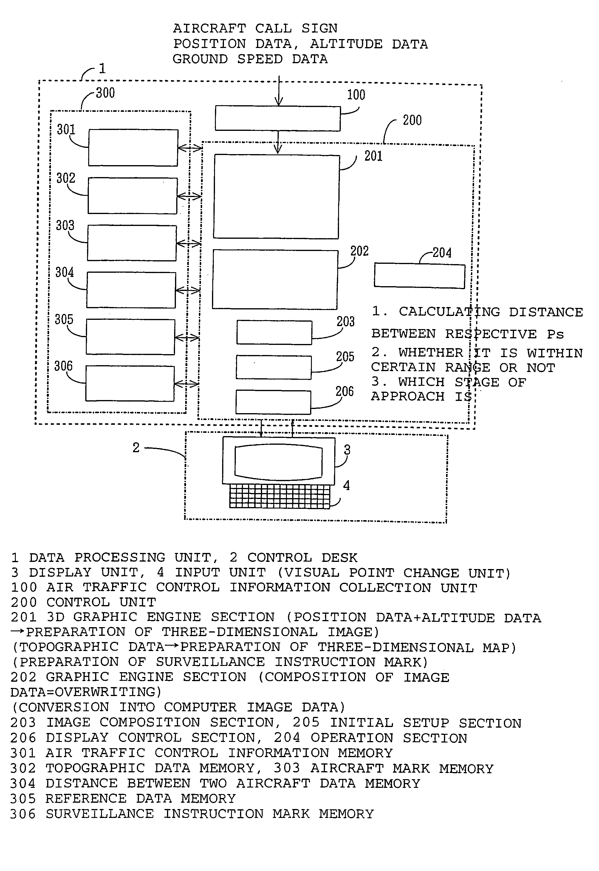
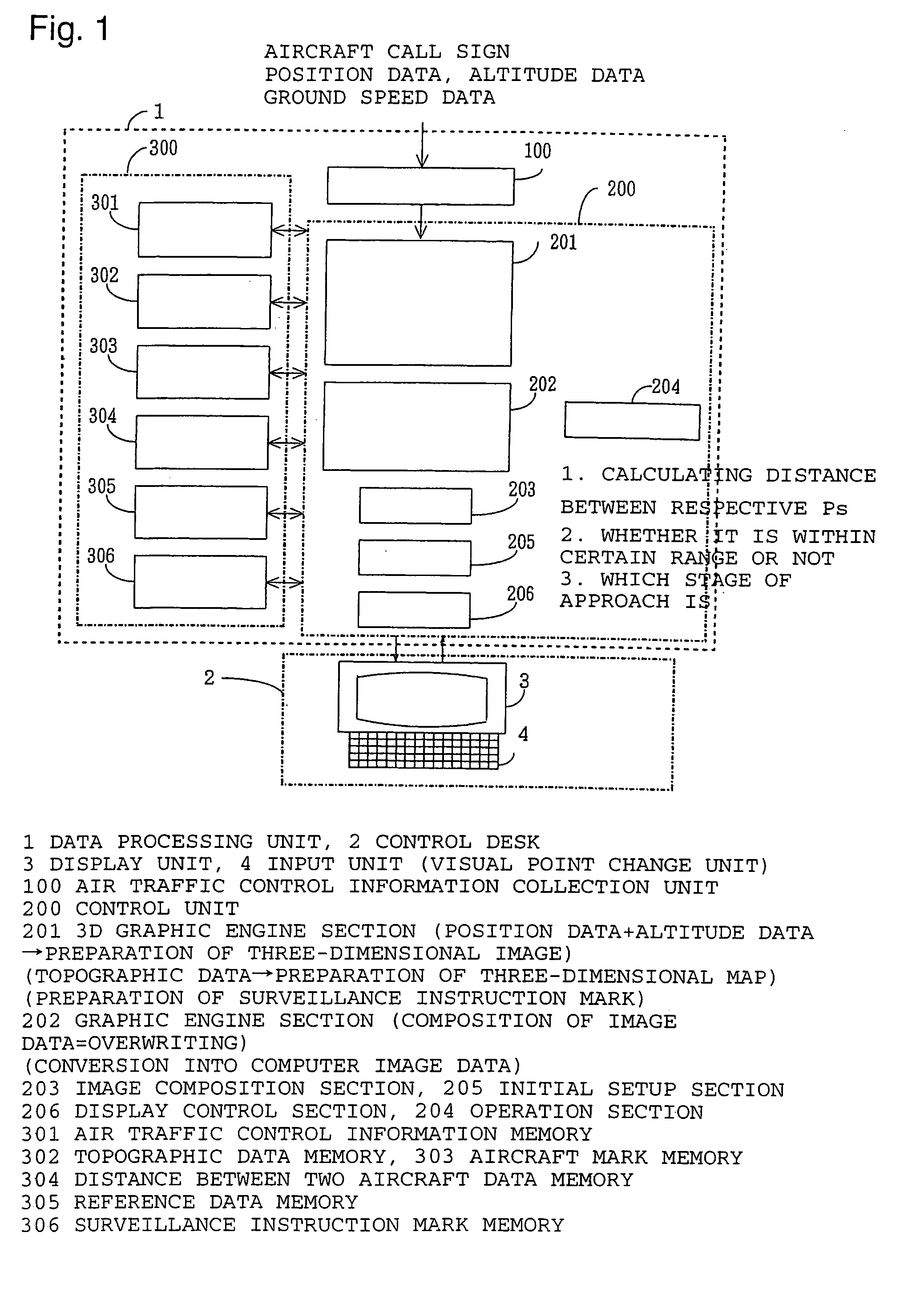
[0037] Turning now to explanation in reference to the accompanying drawings, an aircraft position display system according to the present invention generally comprises a data processing unit 1, a display unit 3 provided on a control console 2, and an input unit 4 connected to the display unit as shown in FIG. 1.

[0038] The data processing unit 1 includes an air traffic control information collection unit 100, a control unit 200 for processing collected air traffic control information for the purpose of accomplishing a desired purpose and for performing control operation, and a storage unit 300 for storing data originally prepared, data to be inputted from outside and data as a result of data processing by the control unit 200, respectively.

[0039] The air traffic control information collection unit 100 collects air traffic control information containing certain data, including the call sign (flight name), the current position, the travel direction and the ground speed of an aircraft...


PUM


Abstract

There is provided a method for displaying aircraft positions, which is capable of effectively avoiding the occurrence of near miss or collision. The method displays the terrain of an air space under air traffic control apparently in three dimensions on a display screen, displays aircraft marks at positions on the display screen so as to correspond to the three-dimensional positions of the respective aircraft, and displays a warning mark when a distance between two aircraft is shorter than a threshold value, wherein the warning mark comprises a triangle having three apexes, which comprise the aircraft marks, and a position that is apart from the aircraft mark of one of the aircraft along a vertical line extending perpendicular to the one aircraft toward a ground surface of the terrain by a distance corresponding to an altitude difference between both aircrafts on the display screen. A certain warning mark may be displayed when protective air spaces for both aircraft are predicted to conflict each other based on flight trajectories and flight conditions.

Description

TECHNICAL FIELD [0001] The present invention relates to a method for displaying aircraft positions in a display system for air traffic control, which is capable of visually grasping the flight status of aircraft under air traffic control on a display screen, and which is particularly appropriate for the surveillance and the air traffic control of the flight status of multiple aircraft that come close to each other within a safety distance. BACKGROUND ART [0002] Tragic accidents by midair collision of aircraft have frequently occurred everywhere in the world. We have often been shocked to hear that near miss has occurred, though midair collision has not occurred fortunately. [0003] In a conventional surveillance radar system, based on air traffic control information obtained from various kinds of radars, multiple range rings indicating a distance from a reference point on a runway on a ground surface, the symbols indicating aircraft under air traffic control, the data tag indicating ...

Claims


Application Information

Patent Timeline
Patent Type & Authority Applications(United States)
IPC IPC(8): G01S7/20G01S13/91G08G5/00G08G5/04
CPCG08G5/0021G08G5/0078G08G5/0052G08G5/0026
Inventor SHIOMI, KAKUICHISAITO, MASANORI
Owner REALVIZ
Why Eureka
Try Eureka