Position detecting method

a detection method and position technology, applied in the field of position detection methods, can solve the problems of poor alignment accuracy, affecting the accuracy of positional detection, and notably displaying noise components in the edge differentiation, so as to reduce the asymmetry of alignment signal asymmetry and accurately detect the position

Inactive Publication Date: 2005-02-17
CANON KK
View PDF13 Cites 16 Cited by
  • Summary
  • Abstract
  • Description
  • Claims
  • Application Information

AI Technical Summary

Benefits of technology

[0015] Accordingly, it is an exemplary object of the present invention to provide a position detecting method that reduces an error in asymmetry of an alignment signal from an alignment mark, and accurately detects a position.

Problems solved by technology

Therefore, a noise component notably appears in the edge differentiation when a high frequency noise is mixed in an alignment signal.
However, a signal processing by pattern matching or the edge differentiation often has a large error about a detection result by asymmetry of an alignment signal (Wafer Induced Shift) by a wafer process, and alignment accuracy often deteriorates.
In other words, when a noise overlaps with an alignment signal, accuracy of a positional detection gets worse.
Since a resist is applied by a spin coat, even if it usually has neither a lumpy wafer surface, nor asymmetry of an alignment mark, nonuniformity of a film thickness occurs near a mark by a level difference of an alignment mark (namely, a concave cross-sectional structure), and causes a systematic noise.
Furthermore, a minute defect and contaminant, etc. can cause a random noise.
Conventionally, an error detected as an asymmetrical waveform in the alignment signal from an alignment mark did not become a big practical problem.
Edge differentiation has high positional detection accuracy, and often receives an influence of a noise.
A position detecting method cannot synthetically perform fine positional detection about an asymmetry (WIS) of an alignment signal.

Method used


Image

  • Position detecting method
  • Position detecting method
  • Position detecting method

Examples


Embodiment Construction

[0040] With reference to accompanying drawings, a description will now be given of a position detecting method of one embodiment according to the present invention. In each figure, the same element is designated by the same reference numeral, and a description thereof will be omitted.

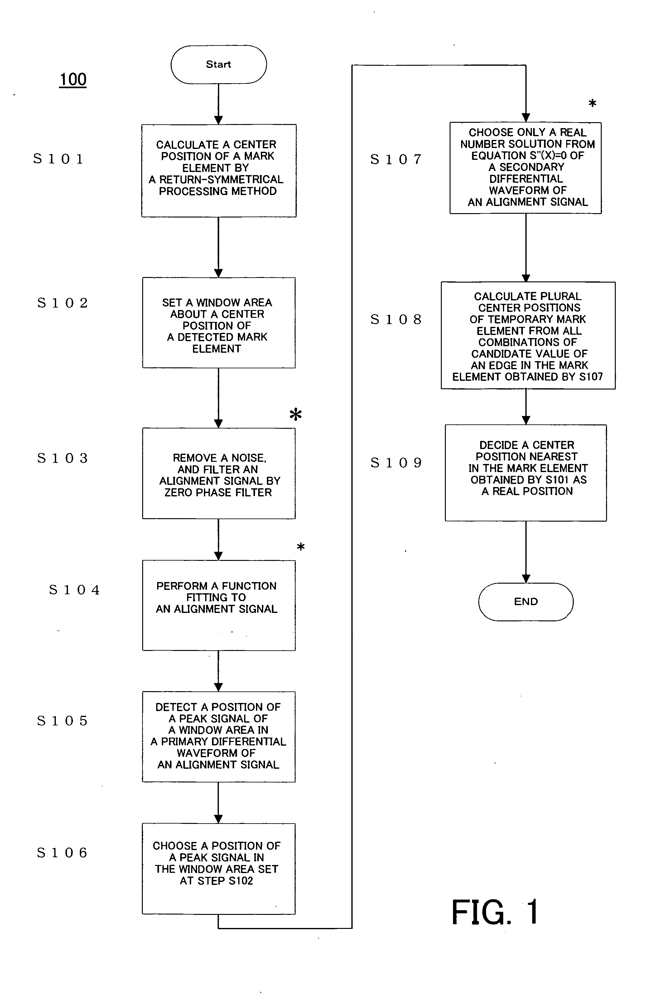
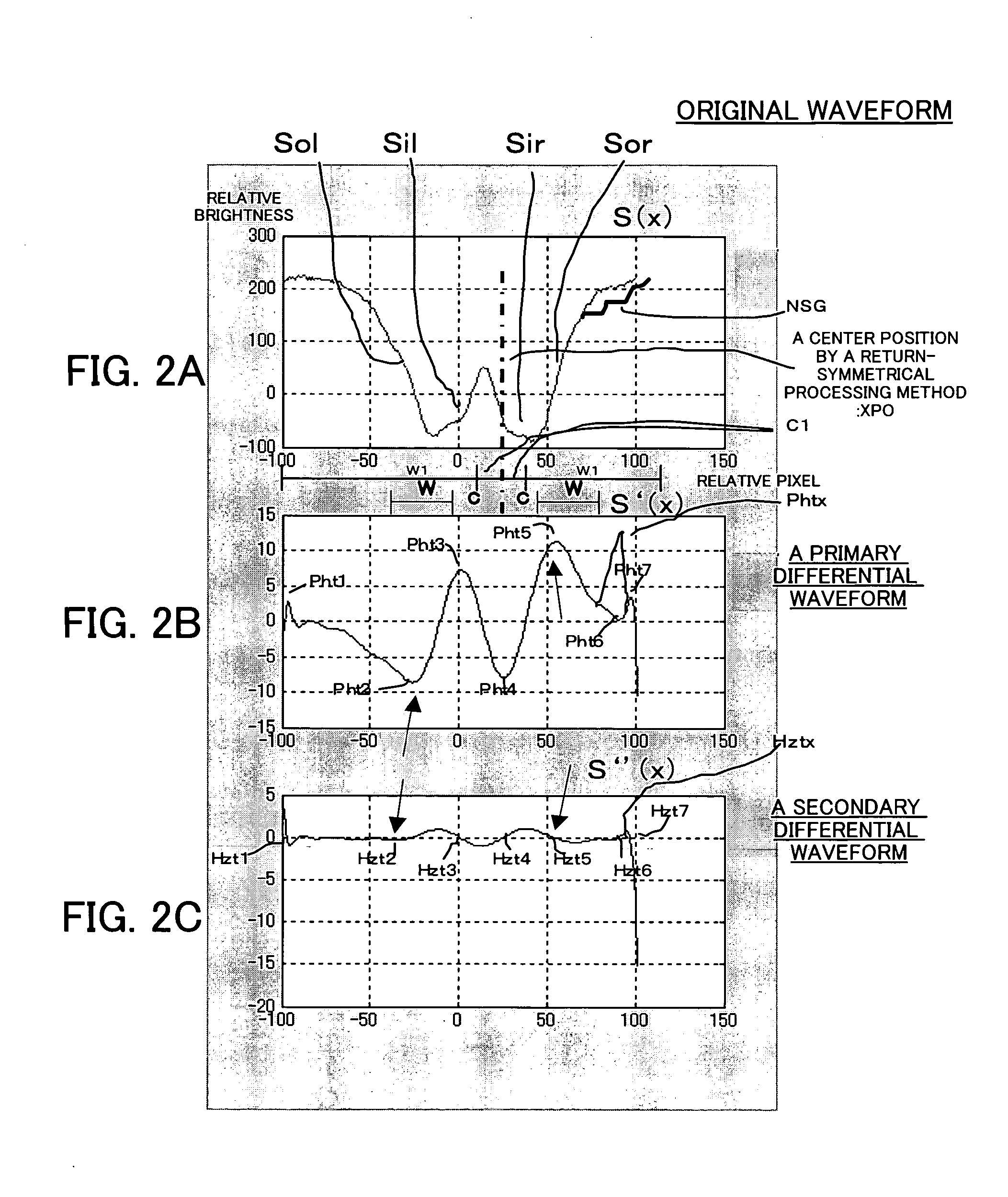
[0041] A detail description will now be given of a return-symmetrical processing method. A return-symmetrical processing method is a kind of signal processing of pattern matching which determines a good position of coincidence by returning a waveform of an alignment signal.

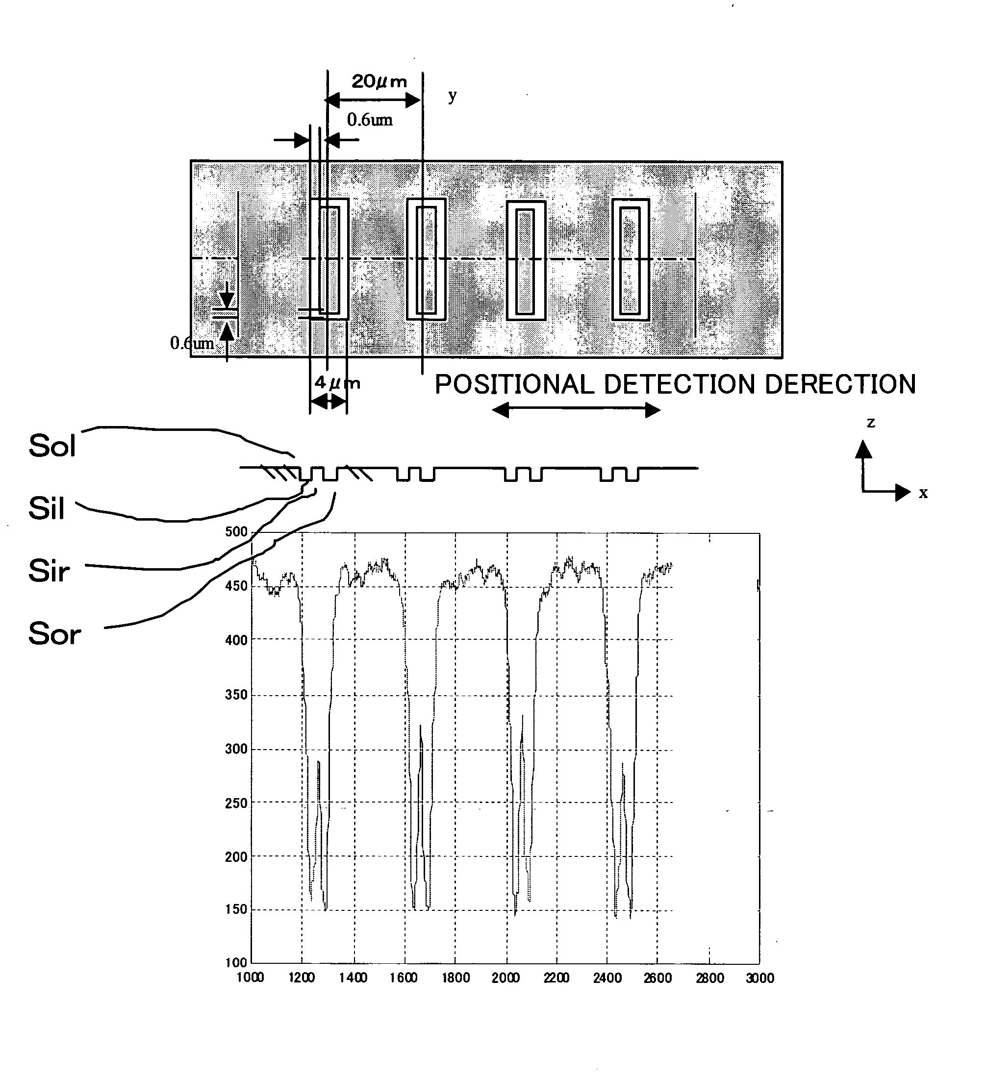
[0042] The return-symmetrical processing method may clearly indicate a position, and finely detect a position when maintaining symmetric property about a center of a pattern (namely, an alignment mark) even if a waveform of the alignment mark changes. When a waveform of an alignment signal asymmetrically changes, a positional detection often has an error because a detected value of an extremal value in a center of a pattern becomes ...


PUM

PropertyMeasurementUnit
wavelengthaaaaaaaaaa

Abstract

A position detecting method for detecting a position of an object to be detected using a signal from an image of an alignment mark which consists of plural mark elements formed on the object, comprising the steps of acquiring first position information indicating a center position approximated from a form of the all signals, acquiring plural second position information indicating a center position in the alignment mark calculated from whole inflection points of the signal, and selecting the second position information as a center position in the alignment mark which is in a predetermined distance based on the first position from the plural second position information.

Description

[0001] This application claims priority benefits based on Japanese Patent Application No. 2003-271889, filed on Jul. 8, 2003, which is hereby incorporated by reference herein in its entirety as if fully set forth herein. BACKGROUND OF THE INVENTION [0002] The present invention relates generally to a position detecting method, and more particularly to a position detecting method for detecting a position of objects, such as a wafer, in the exposure apparatus used for manufacturing various devices, such as semiconductor chips as IC and LSI, a liquid crystal display (LCD), CCD, and a magnetic head. This invention is suitable for relative alignment between a reticle and wafer. [0003] The demand for fine semiconductor elements used in an electric device has been greater because an electric devices have become thinner in shape. A conventional projecting exposure apparatus for projecting a circuit pattern of a reticle or a mask onto a wafer etc. by projecting optical system, and for transfe...

Claims


Application Information

Patent Timeline
Patent Type & Authority Applications(United States)
IPC IPC(8): G03F9/00G01B11/00H01L21/027
CPCG03F9/7092
Inventor SUZUKI, TAKEHIKO
Owner CANON KK
Why Eureka
Try Eureka