Current sharing method and apparatus for alternately controlling parallel connected boost PFC circuits

a power factor correction and parallel connection technology, applied in the direction of electric variable regulation, process and machine control, instruments, etc., can solve the problems of unbalanced currents of the two sub-circuits, relatively more serious phenomenon, and relatively complex circuit configurations, and achieve the effect of high efficiency of the dual boost pfc circui

a power factor correction and parallel connection technology, applied in the direction of electric variable regulation, process and machine control, instruments, etc., can solve the problems of unbalanced currents of the two sub-circuits, relatively more serious phenomenon, and relatively complex circuit configurations, and achieve the effect of high efficiency of the dual boost pfc circui

US20050036337A1Active Publication Date: 2005-02-17DELTA ELECTRONICS INC

Image

  • Current sharing method and apparatus for alternately controlling parallel connected boost PFC circuits
  • Current sharing method and apparatus for alternately controlling parallel connected boost PFC circuits
  • Current sharing method and apparatus for alternately controlling parallel connected boost PFC circuits

Examples


Embodiment Construction

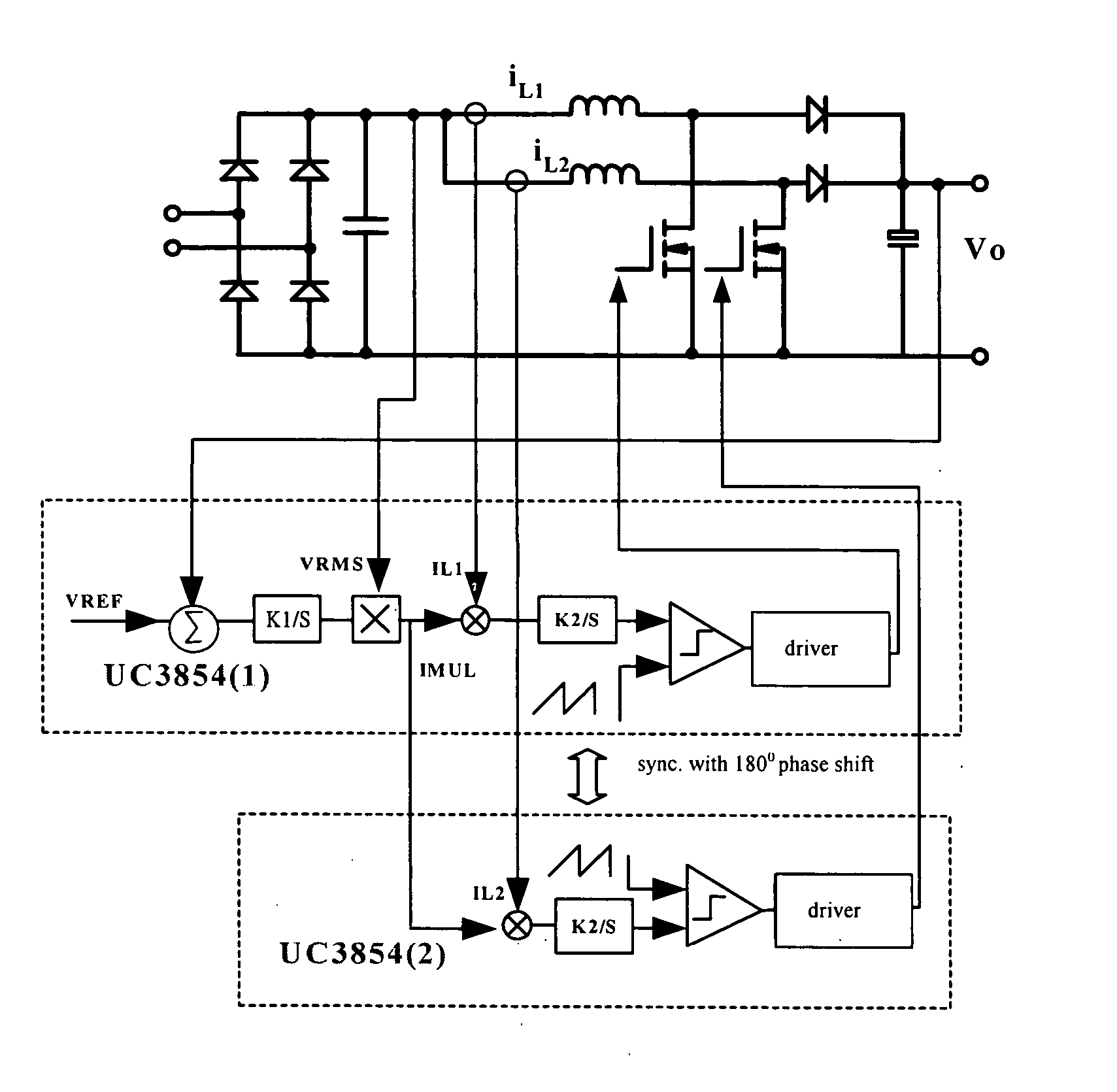
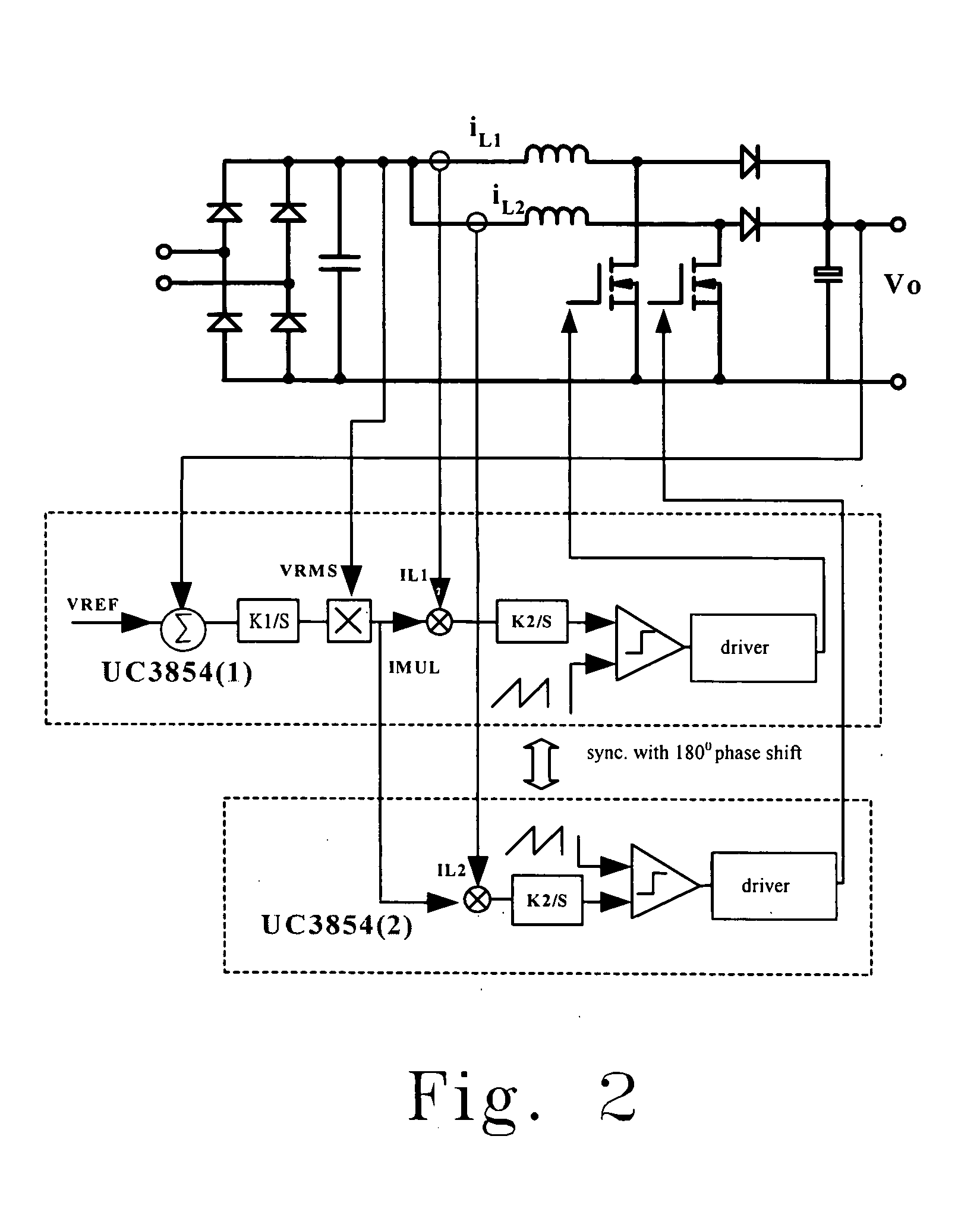
[0031] The controlling alternative of the present invention is described as follows: 1. sampling the inductor current of the two parallel connected sub-circuits; 2. employing two control ICs (e.g., UC3854) respectively control two power switches. The main difference among the proposed method and the aforementioned methods in the prior arts is that the two control ICs in the present invention share the same current reference, IMUL, as shown in FIG. 2.

[0032] Two control ICs share the same current reference will make sure that the two inductor currents respectively flowing on one of the two sub-circuits are equal so as to accomplish the current sharing. After employing two of the commonly used control ICs, UC3854s, to control, the two inductor currents respectively flowing on each sub-circuit could track the rectifying voltage relatively good, and the two average values of the currents respectively flowing on the two inductor are equal, thus the total inductor current can be employed ...


PUM


Abstract

The provided method and control circuit are employed to alternately control the dual boost PFC circuits. The control circuit for alternately controlling parallel-connected first and second boost circuits of a dual boost PFC circuit to achieve a current-sharing of the first and the second boost circuits includes: a first control circuit having a first current control loop for employing an output voltage of the PFC circuit, a feed-forward voltage, and an input reference voltage to generate a current reference, and sending the current reference to an input terminal of the first current control loop to generate a first PWM signal to drive the first boost circuit, and a second control circuit having a second current control loop for receiving the current reference through an input terminal of the second current control loop to generate a second PWM signal to drive the second boost circuit.

Description

FIELD OF THE INVENTION [0001] The present invention relates to the current-sharing method and the control circuit for alternately controlling the power factor correction (PFC) circuits. More specifically, this invention relates to the current-sharing method and the control circuit for alternately controlling the dual boost PFC circuits. BACKGROUND OF THE INVENTION [0002] The traditional boost PFC circuits are widely used due to their unique features of: simplicity, capability of boosting the voltages, and relatively higher efficiency. Following that the relatively higher power levels of the power sources are more and more desired, several of these modulated boost PFC circuits are required to be coupled in series or in parallel usually. For example, three-level boost PFC circuits are usually employed to let the voltage stresses of the switches be limited to a half of the output voltage in the high voltage applications. In which, apparatuses respectively composed of several boost conv...

Claims


Application Information

Patent Timeline
17 Feb 2005
Publication
US20050036337A1
IPC
H02M3/158; H02M3/335
CPC
H02M2003/1586; H02M3/1584; H02M1/4225; Y02B70/10; Y02P80/10; H02M3/1586
Inventors
ZHANG, QINGYOU; QIU, AIBIN