Drive unit comprising an electric motor for adjusting devices in motor vehicles
a technology of electric motors and drive units, which is applied in the direction of control/drive circuits, door/window accessories, door/window fittings, etc., can solve the problems of considerable current force through, high cost of electronic commutating circuits, and difficulty in maintenance-free electronic commutating motors. achieve the effect of cost-effective manufacture and us
Inactive Publication Date: 2005-02-24
BROSE FAHRZEUGTEILE GMBH & CO KG
View PDF7 Cites 24 Cited by
- Summary
- Abstract
- Description
- Claims
- Application Information
AI Technical Summary
Benefits of technology
[0006] The object of the present invention is to provide a compact, lightweight drive unit which is cost-effective to manufacture and use and which includes an electric motor, power supply device, gearing and electronics with integrated power supply, control and regulating action for the drive unit as well as control and monitoring of the adjusting device driven by the drive unit.
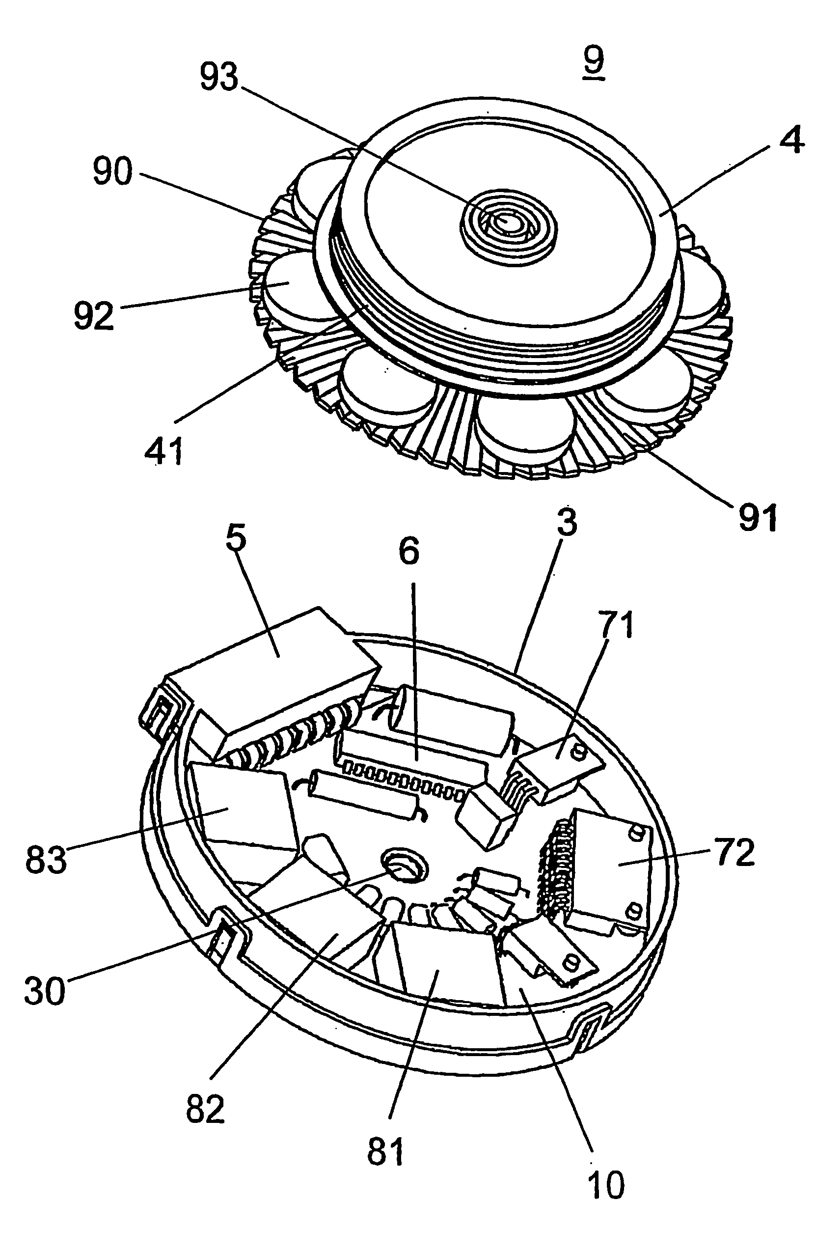
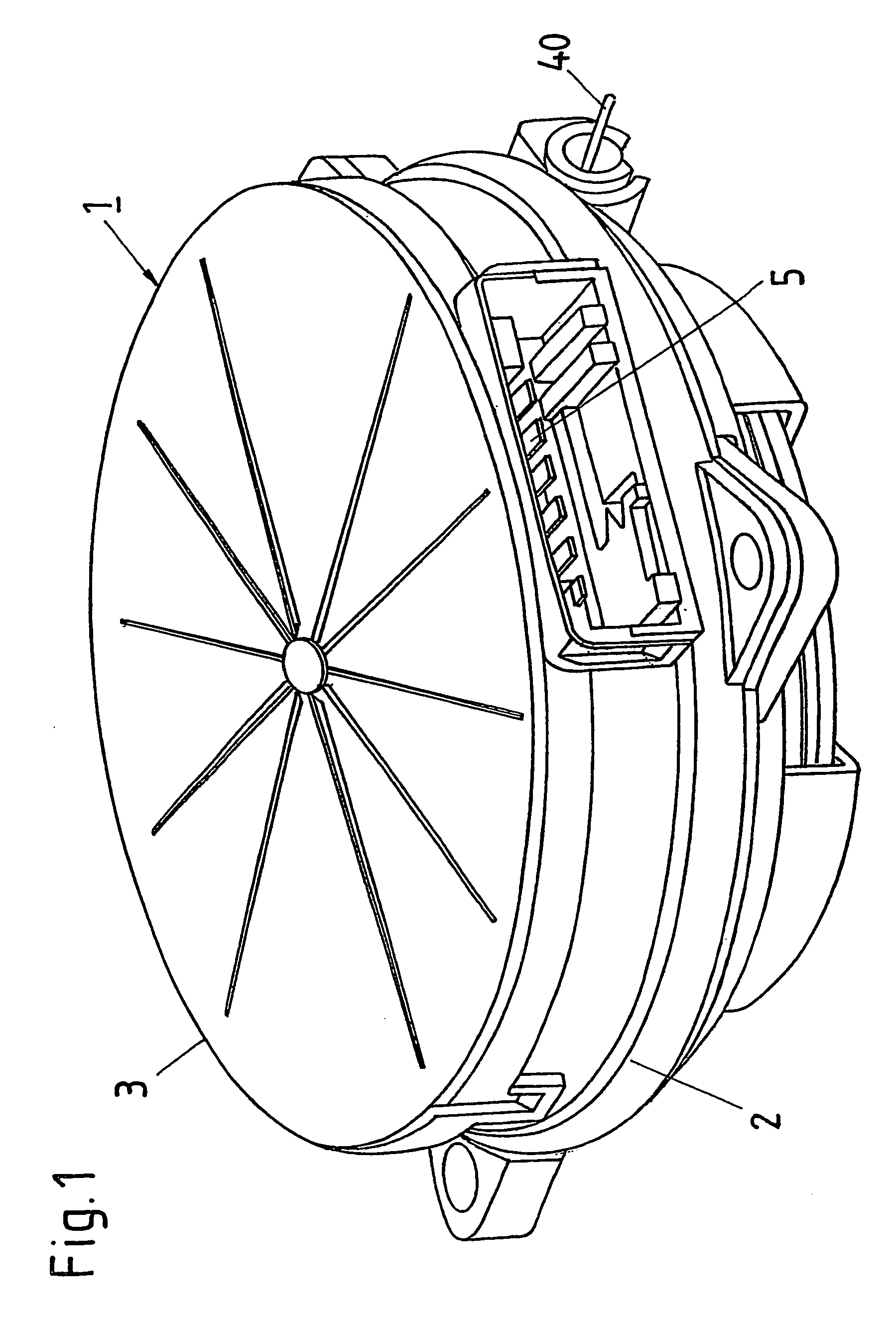
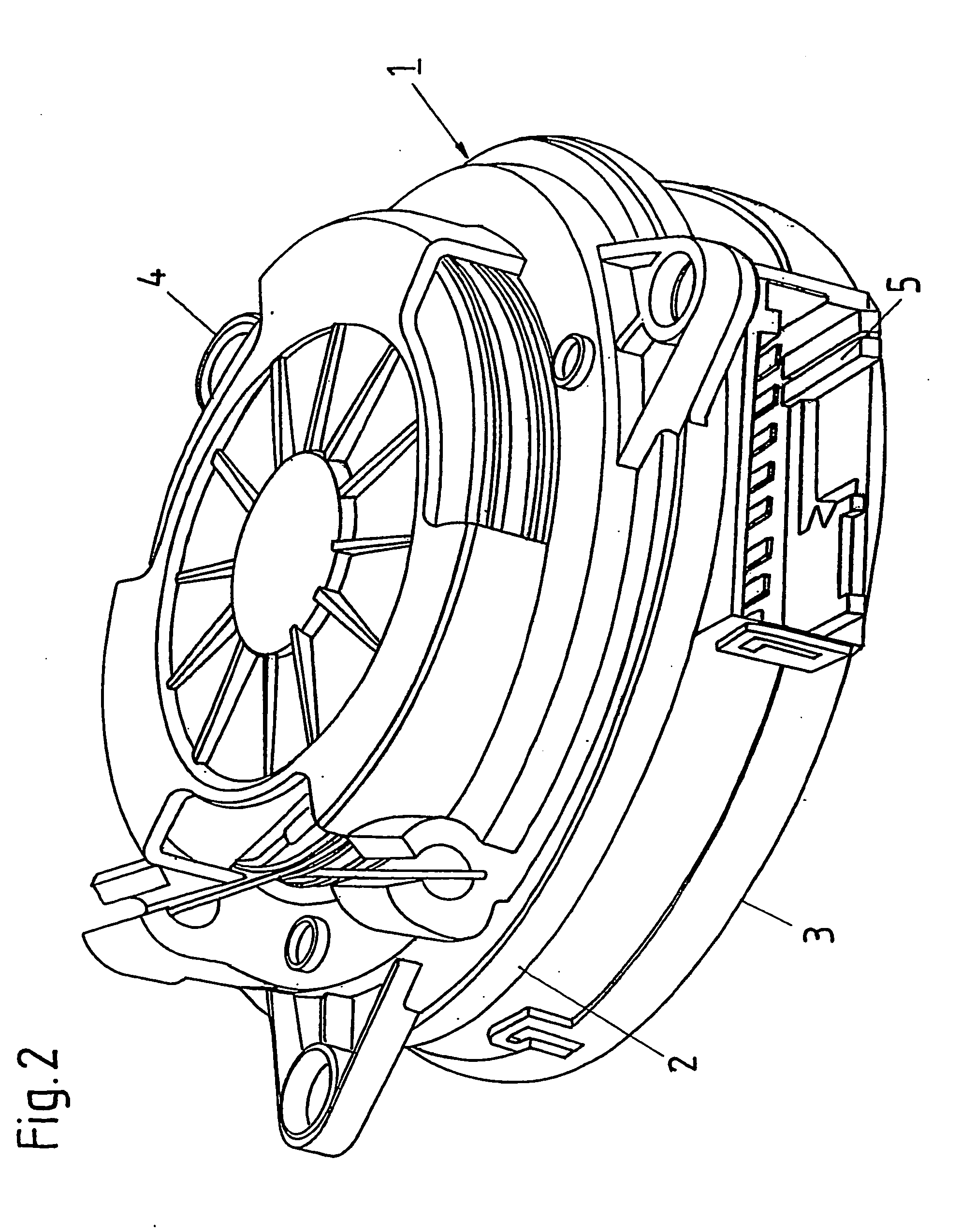
[0007] The solution according to the invention provides a compact, lightweight drive unit which is cost-effective to manufacture and use and which includes an electric motor, power supply device, gearing and electronics with integrated power supply, control and regulating action of the drive unit as well as control and monitoring of the adjusting device driven by the drive unit. Since the drive unit combines all the component parts required for the power supply, control and regulation of the drive unit as well as control and monitoring of the adjusting device in one housing, the prerequisites are provided for a synergetic fusion of electronic components with, for example, anti-nip protecting electronics as well as electronics and mechanical components such as parts supporting the housing of the electric motor and the electronic components. As such, the drive unit can be operated in conjunction with the adjusting device driven by same in the manner of a servo motor. Through the synergetic combining of the current rectifier circuit, which is required for electronic commutation but which increases costs, with a monitoring electronics unit for the adjusting device driven by the drive unit a cost effective manufacture of the overall system is possible.
Problems solved by technology
The use of maintenance-free electronically commutated motors has been problematic, given on the one hand the on-board mains voltage available up to now of 12 V in motor vehicles, and on the other hand the costs for such electronic commutating circuits.
With this low voltage, considerable currents have to be forced through the electronic commutation circuit as a result of the power required.
For both mechanically commutated electric motors and electronically commutated electric motors for use with adjusting devices in motor vehicles, a considerable amount of space has to be provided to include the gear parts required for the adjusting devices.
In addition, as a result of the markedly different surrounding conditions during operation, and owing to the operating safety required for such drive units, a considerable manufacturing expense is also incurred.
Method used
View moreImage
Smart ImageViewing Examples

Examples
first embodiment
[0041] In a first embodiment for brush-commutated machines, contact with the brushes 11 and 12 is produced through the contacts of the electronic component 15 and the plug or plug system 5, and the electronic component 15 contains common components for controlling and regulating the brush-commutated electric motor and anti-jam protection device.
second embodiment
[0042] In a second embodiment for electronically commutated machines, contact is produced through the contact of the electronic component 15 and the plug or plug system 5 with the power switches and coils of the electronics unit which contains both an anti jam circuit and a circuit for controlling the electronically commutated electric motor, so that a so-called “mechatronic unit” is formed.
Login to View More PUM
 Abstract
The invention relates to a drive unit comprising an electric motor (9), a power supply device that supplies power to the electric motor (9), at least one gear or driven gear (4) that is connected to the electric motor (9) and electronics for adjusting devices in motor vehicles. In said device, the electronics and the power supply device (5, 6, 15; 71-83) are integrated into the housing (1) of the electric motor (9) and said electronics and power supply device (5, 6, 15; 71-83) carry out both control and regulatory functions of the electric motor (9) and control, regulatory and monitoring functions of the adjusting devices.
Description
CROSS-REFERENCE TO RELATED APPLICATION(S) [0001] This application is a National Phase Patent Application of International Application Number PCT / DE02 / 03473, filed on Sep. 11, 2002, which claims priority of German Patent Application Number 101 47 225.0, filed on Sep. 14, 2001.BACKGROUND OF THE INVENTION [0002] An electric motor is known from DE 28 31 774 C2 with a disc rotor in the flat air gap having a non-ferrous stator winding which is associated at least on one side with a permanent magnetic ring with an axially magnetised segment and on both sides with soft-magnetic flat discs for the magnetic reflux. Coaxial with the rotor shaft is an electrodynamic tachogenerator which is arranged so that the most compact combination possible is produced for the electric motor and tachogenerator. [0003] The known combination of electric motor and tachogenerator includes the coaxial function elements of the electric motor and tachogenerator arranged in a row, whereby each unit is fully function...
Claims
Login to View More Application Information
Patent Timeline
 Patent Type & Authority Applications(United States)
IPC IPC(8): E05F15/00E05F15/16E05F15/60H02K5/22H02K11/04H02K11/33H02P6/12
CPCE05Y2900/55H02K5/225H02K11/0073E05F15/697E05F15/40E05F15/60E05Y2900/50H02K11/33
Inventor SESSELMANN, HELMUT
Owner BROSE FAHRZEUGTEILE GMBH & CO KG