Rotor bush, motor equipped therewith, and manufacturing methods therefor

a technology of rotor bush and motor, which is applied in the direction of dynamo-electric machines, magnetic circuit rotating parts, and shape/form/construction of magnetic circuits, etc., can solve the problems of bush burrs or shaft bending, shaft damage, and shaft flaws, so as to reduce the wear of bearings and noise during rotation

Inactive Publication Date: 2005-02-24
MABUCHI MOTOR
View PDF6 Cites 0 Cited by
  • Summary
  • Abstract
  • Description
  • Claims
  • Application Information

AI Technical Summary

Benefits of technology

[0019] An object of the present invention is to solve these problems and to provide a rotor bush whose bearing pressure is lowered by eliminating any seam in the circumferential direction and keeping the bush in contact with the bearing face to face, resulting in reductions in the wear of the bearing and the noise during rotation.
[0020] Another object of the invention is to provide a rotor bush whose parallelism can be readily maintained and which makes it easy to keep parallelism and difficult to allow any inclination relative to the bearing face and is enhanced in resistance to pressure to shift by being brought into contact with the shaft face to face.
[0021] Still another object of the invention is not only to restrain the occurrence of shaft flaws, bush burrs or shaft bending by reducing the interference between the shaft and the rotor bush but also to improve the sticking of the insulative coat by making possible the use of ferrous material and thereby enabling rotor bush to be directly heated with a high frequency wave.

Problems solved by technology

However, if a large interference (=outer diameter of shaft−bore of rotor bush) is set, shaft flaws, bush burrs or shaft bending may arise.
Or where a rotor bush of a hard material, such as iron, is used, unless it is pressed in with a reasonably weak force, the shaft may be injured.
On the other hand, if the pressing force is too weak, the intention of placing the rotor bush in its tentative position cannot be achieved.
However, in an actual manufacturing process, it is difficult to keep the interference at a prescribed level of precision.
For this reason, the shaft 1 is heated with a high frequency wave, and the coating is accomplished with heat transmitted from the shaft 1, resulting in poor sticking of the insulative coat.
However, as this C ring 22 is formed by shaping a piano wire in a C shape, the part of it in contact with a bearing 13 has no flat face and accordingly its contact with the bearing 13 is only by points, resulting in a high bearing pressure and an ensuing problem that the bearing 13 is easily worn out.
In addition, because the C ring 22 and the shaft 1 are in contact with each other only by points, when the C ring 22 is fitted, it is difficult to achieve parallelism, and the ring tends to incline relative to the bearing face.
There is an additional problem that the resistance to the pressure to shift is low (the C ring 22 is apt to be shifted on the shaft 1 in the axial direction).

Method used


Image

  • Rotor bush, motor equipped therewith, and manufacturing methods therefor
  • Rotor bush, motor equipped therewith, and manufacturing methods therefor
  • Rotor bush, motor equipped therewith, and manufacturing methods therefor

Examples


Embodiment Construction

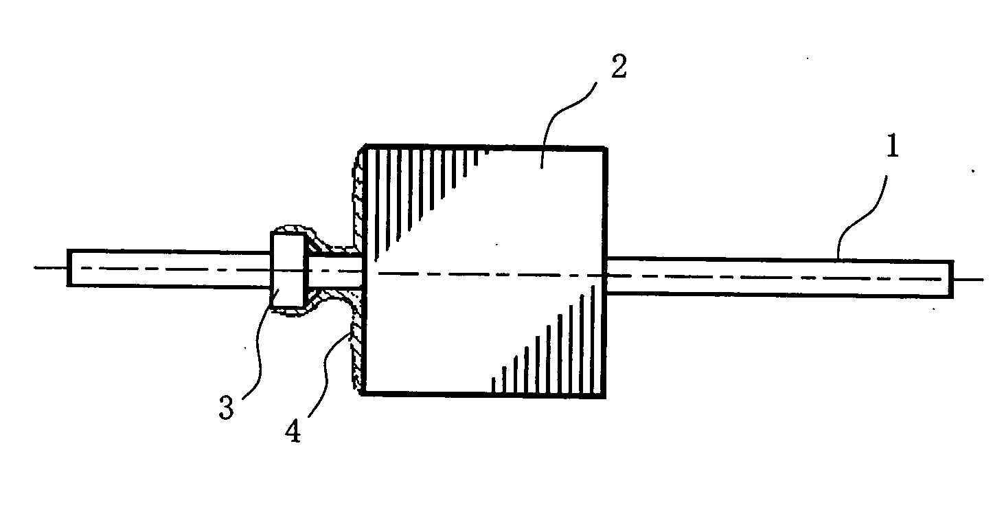
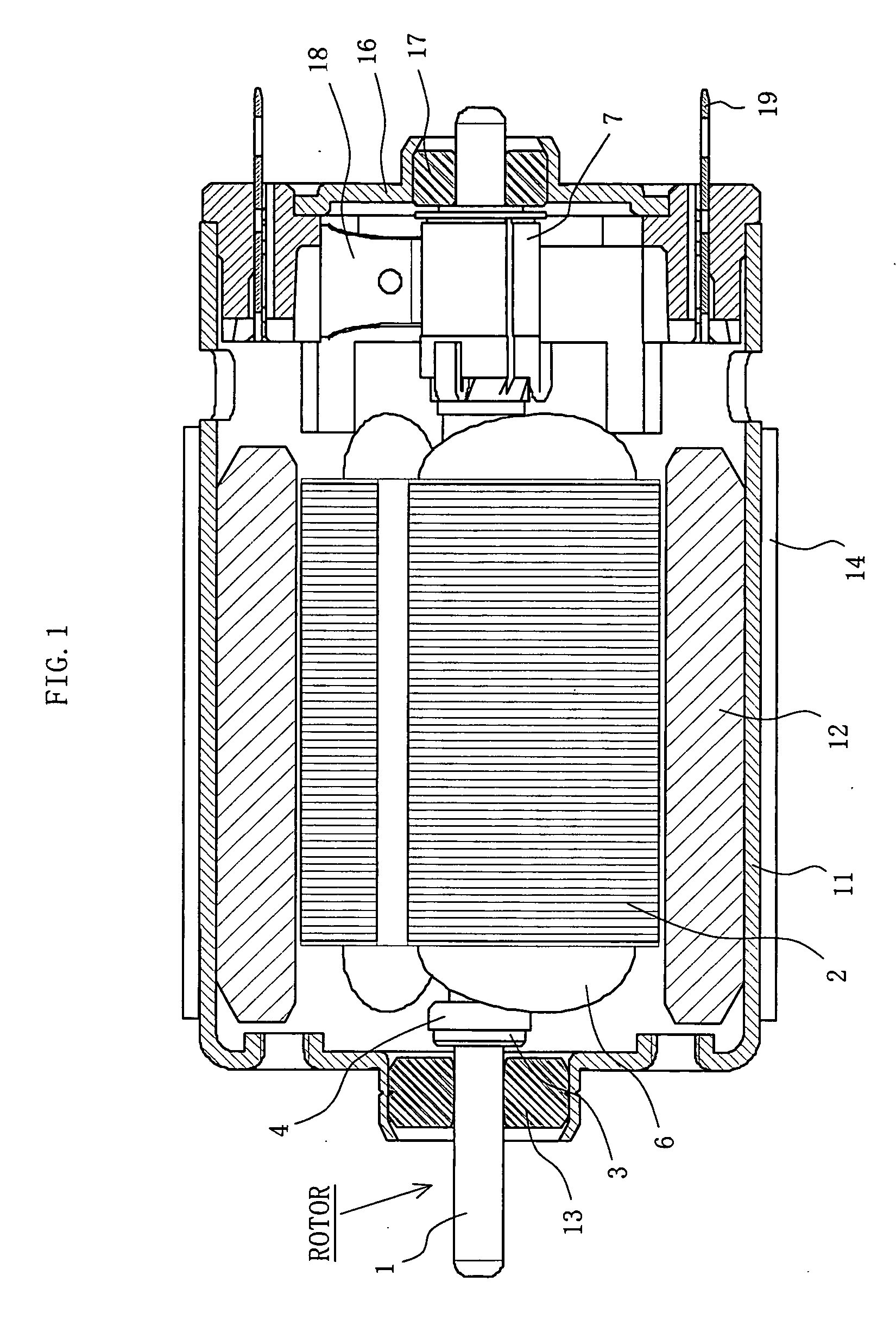
[0046]FIG. 1 schematically shows a vertical section of a small motor to which the present invention is to be applied, and this motor has a usual motor configuration except for the rotor bush. A rotor is configured by fitting a core 2, a coil 6 and a commutator 7 onto a shaft 1. In the drawing, reference numeral 3 denotes a rotor bush which positions the rotor in the axial direction, over which an insulative coat 4 is applied.

[0047] In the drawing, reference numeral 11 denotes a cylindrical hollow metallic motor case having a bottom, to whose inner circumferential face is fixed a magnet 12 (illustrated to be bipolar) to serve as a stator magnetic pole, and at the center of the bottom of the motor case 11 is integrally disposed a cylindrical protruding section for accommodating the bearing 13, i.e. the bearing supporting section. Reference numeral 14 denotes a yoke, which is formed of a highly magnetic material, such as an iron sheet, in a substantially cylindrical shape and firmly s...


PUM


Abstract

In order to position the rotor of the motor in the axial direction of the shaft, the rotor bush is placed in a prescribed position. This rotor bush comprises, all integrally machined from a planar metallic material, a shaft-contacting cylindrical wall section whose inner circumferential face constitutes a shaft press-in hole, a bearing-contacting section linked to an end of the shaft-contacting cylindrical wall section and formed in a planar shape, an outer cylindrical wall section extending from the outer circumferential side of the bearing-contacting section, and a plurality of claws formed at an end of the outer cylindrical wall section. By pressing the shaft into the shaft press-in hole of this rotor bush and bending and caulking the claws toward the surface of the shaft, the rotor bush is fixed to the shaft.

Description

BACKGROUND OF THE INVENTION [0001] 1. Field of the Invention [0002] The present invention relates to a rotor bush fixed, in order to position a rotor in the axial direction of a shaft, in a prescribed position of the shaft in the axial direction, a motor equipped therewith, and manufacturing methods for the rotor bush and the motor. [0003] 2. Description of the Related Art [0004] There is known a technique applicable to a small motor for use in a power tool, drier, printer or the like by which a rotor is positioned in the axial direction by fixing the rotor bush on the rotor shaft and supporting this rotor bush in the thrust direction with a bearing. [0005]FIG. 11 and FIG. 12 illustrate a rotor bush embodying a first example of the prior art (see Patent Reference 1). FIG. 11 shows a state in which a rotor bush 21 is fitted on a shaft 1 to which a core 2 is fitted, and FIGS. 12(A) and 12(B) show sectional views of different rotor bushes each by itself. [0006] A rotor bush 21 having a...

Claims


Application Information

Patent Timeline
Patent Type & Authority Applications(United States)
IPC IPC(8): H02K1/28H02K1/30H02K15/02
CPCH02K1/28
Inventor FURUYA, KENJIYASAKU, NORIYUKI
Owner MABUCHI MOTOR
Why Eureka
Try Eureka