
Method and apparatus for recording a sequence of images using a moving optical element

a technology of moving optical elements and sequences, which is applied in the field of methods and apparatus for recording sequences of images using moving optical elements, can solve the problems of limited dynamic range for measuring brightness, color, and limited spatial resolution of typical imagers, and achieve enhanced resolution and dynamic range, and spatial resolution. enhanced

Active Publication Date: 2005-02-24
THE TRUSTEES OF COLUMBIA UNIV IN THE CITY OF NEW YORK
View PDF8 Cites 53 Cited by
  • Summary
  • Abstract
  • Description
  • Claims
  • Application Information

AI Technical Summary

Benefits of technology

It is therefore an object of the present invention to provide an imaging system having enhanced spatial resolution, as well as enhanced resolution and dynamic range with respect to color, polarization, depth, and brightness.
It is a further object of the present invention to provide an imaging system which provides such enhanced resolution and dynamic range without substantially reducing the rate at which images can be recorded.

Problems solved by technology

Conventional imagers suffer from shortcomings with respect to the quality of data they can produce.
For example, a typical imager has limited spatial resolution and has limited dynamic range for measuring the brightness, color, and polarization of light.
Furthermore, most non-stereoscopic imagers are unable to measure scene depth—i.e., the distance between the imager and the object being imaged.
Such limitations render many conventional imagers inadequate for certain computational vision tasks such as, for example, feature detection, object recognition, motion measurement, and scene reconstruction.
However, such a filtering technique tends to be cumbersome, because the filters 2106 must be sufficiently large to cover the field of view of the camera 2108.
This requirement makes the filter wheel 2104 bulky and heavy, and therefore, a substantial amount of energy is required to move the filter wheel 2104 between frames.
As a result, the frame rate of the system tends to be too slow for real-time imaging.
Furthermore, synchronization requires additional timing circuitry.

Method used


Image

  • Method and apparatus for recording a sequence of images using a moving optical element
  • Method and apparatus for recording a sequence of images using a moving optical element
  • Method and apparatus for recording a sequence of images using a moving optical element

Examples


Embodiment Construction

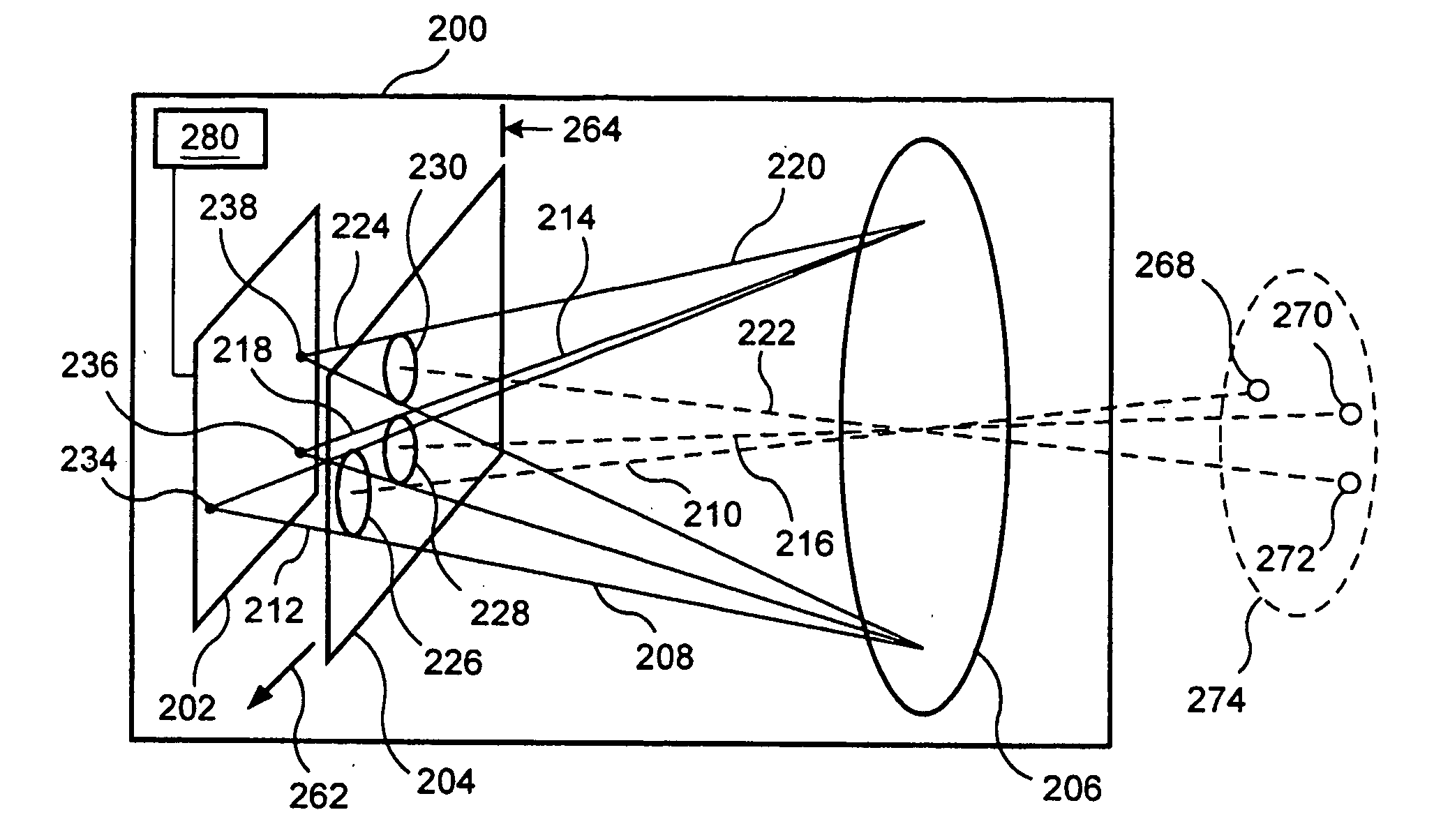
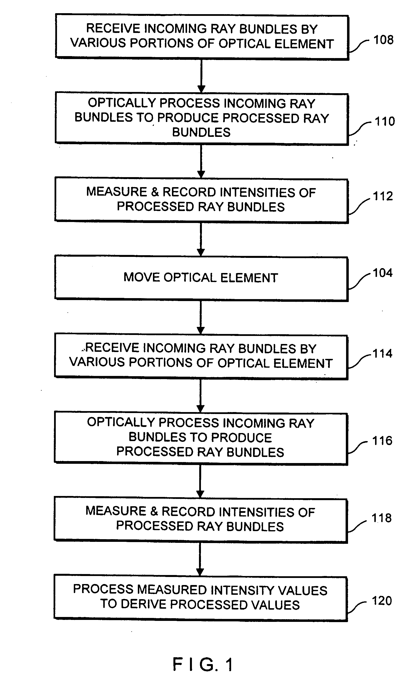
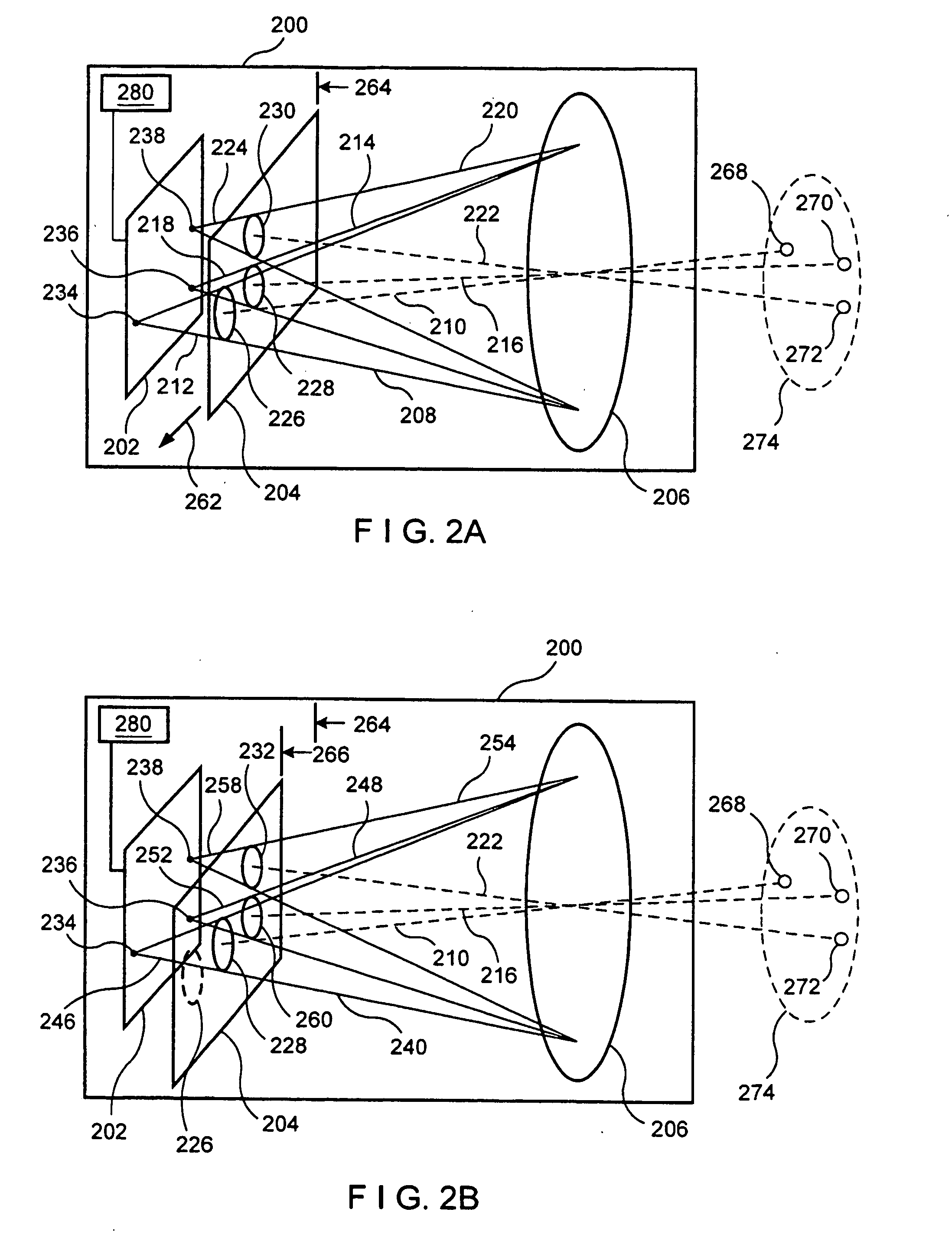
FIG. 2A illustrates schematically an exemplary imager 200 for recording images in accordance with the present invention. The imager 200 includes a lens 206, an image detector 202, and an optical element 204 which can be moved in the reference frame of the imager 200. The optical element 204 is used to process incoming radiation rays (e.g., visible light rays, infrared rays, ultraviolet rays and / or other types of radiation rays), thereby producing processed rays which are received by the image detector 202. The image detector 202 measures the intensities of the processed rays in order to produce images. The image detector 202 is preferably an electronic detector such as a charge-coupled device (CCD) array. The imager 200 is operated by recording multiple images—i.e., a sequence of image frames—while moving the optical element 204 in the reference frame of the imager 200, as is described in further detail below.

In considering the imager 200 illustrated in FIG. 2A, it should be noted ...


PUM


Abstract

An imager (200) including a spatially varying optical element (204) which moves while the imager records a sequence of images. The optical element (204) can be an intensity reduction filter, a spectral or polarization filter, or a refractive or reflective element. Because the optical element (204) moves between frames, each scene portion is captured under a range of imaging conditions. A spatially varying intensity reduction filter enables imaging of each scene portion using multiple, different exposure to generate a high dynamic range image. A spatially varying spectral or polarization filter enables measurement of the spectral or polarization characteristics of radiation from each scene portion. A refractive or reflective element enables imaging of scene portions under various focal characteristics, thereby providing depth information and producing an image which is focused everywhere. A refractive or reflective element is used to apply different vertical and / or horizontal shifts to the different frames, thereby generating an enhanced-resolution image.

Description

BACKGROUND OF THE INVENTION Conventional imagers suffer from shortcomings with respect to the quality of data they can produce. For example, a typical imager has limited spatial resolution and has limited dynamic range for measuring the brightness, color, and polarization of light. For example, conventional cameras can have spatial resolution as low as 640×480 pixels, and color resolution as low as 8 bits. Furthermore, most non-stereoscopic imagers are unable to measure scene depth—i.e., the distance between the imager and the object being imaged. Such limitations render many conventional imagers inadequate for certain computational vision tasks such as, for example, feature detection, object recognition, motion measurement, and scene reconstruction. Efforts have been made to enhance the quality of image data generated by video and still cameras. For example, in order to enhance the resolution and dynamic range of image data, and / or to provide additional information such as polari...

Claims


Application Information

Patent Timeline
IPC IPC(8): G01J3/28G02B5/20H04N5/217H04N5/225H04N5/235H04N5/238H04N5/349H04N5/353H04N5/355H04N5/372H04N9/04
CPCG01J3/2823G01J2003/1217G01J2003/1243G02B5/205H04N9/045H04N5/2254H04N5/2353H04N5/2355H04N5/238H04N5/217H04N23/81H04N23/55H04N23/741H04N23/75H04N23/73
Inventor NAYAR, SHREE K.SCHECHNER, YOAV Y.
Owner THE TRUSTEES OF COLUMBIA UNIV IN THE CITY OF NEW YORK
Learn More