Loudspeaker

Active Publication Date: 2005-02-24
PANASONIC CORP
View PDF46 Cites 27 Cited by
  • Summary
  • Abstract
  • Description
  • Claims
  • Application Information

AI Technical Summary

Benefits of technology

[0009] Therefore, an object of the present invention is to provide a loudspeaker with an elong

Problems solved by technology

Accordingly, the diaphragm and the voice coil are separated from each other, resulting in an increase in distortion of the diaphragm during vibration or causing insufficient vibration.
Note that particularl

Method used


Image

  • Loudspeaker
  • Loudspeaker
  • Loudspeaker

Examples


Example

[0047] (First Embodiment)

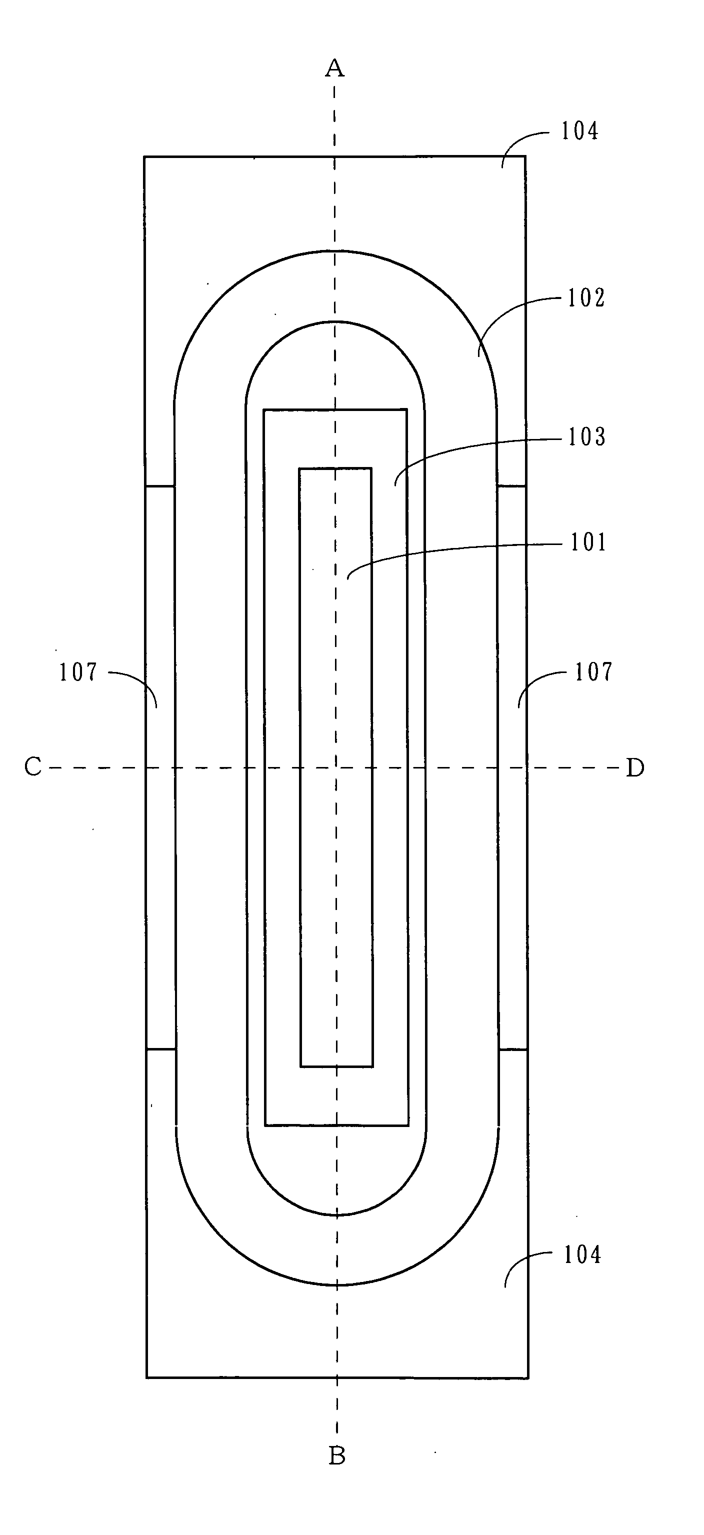
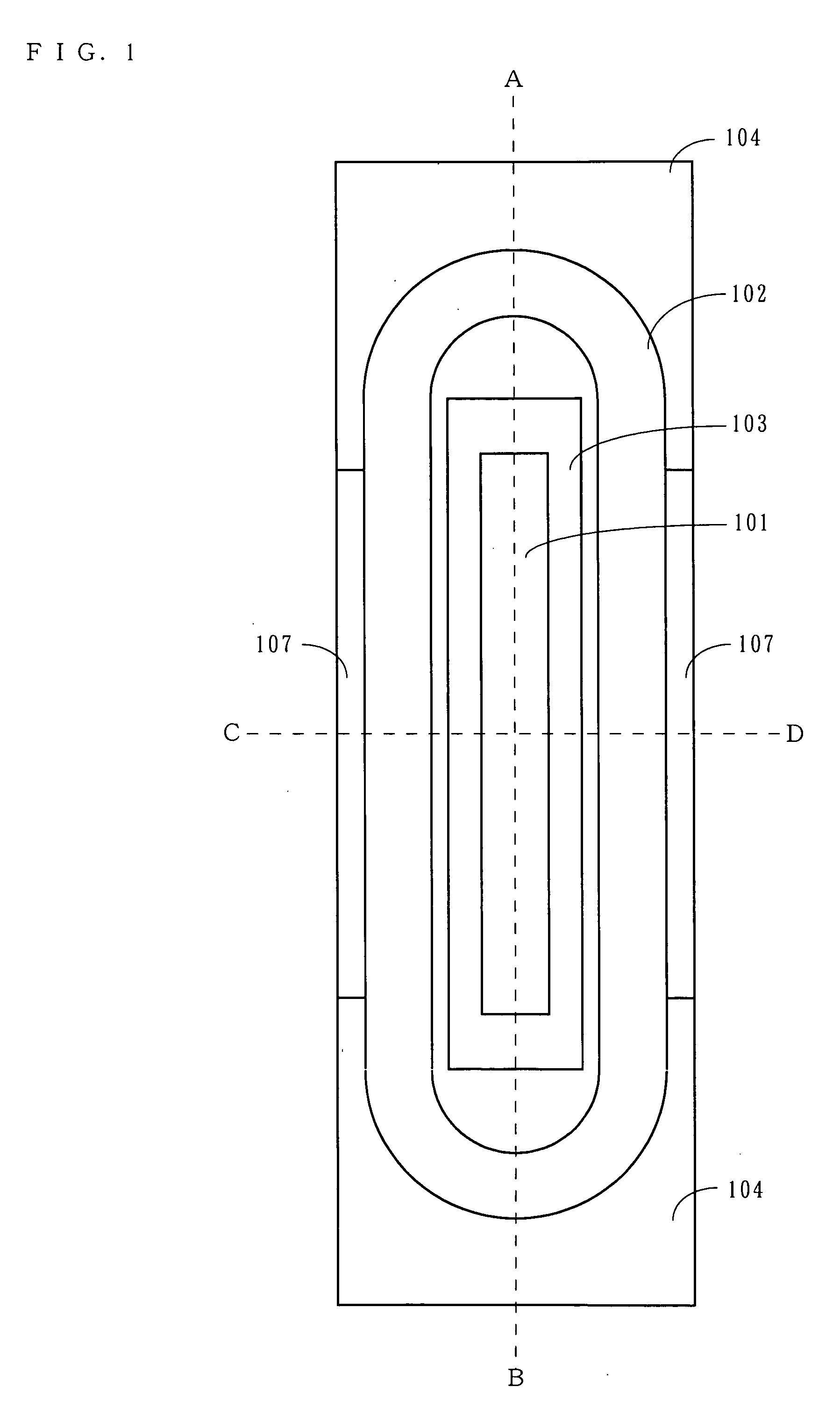
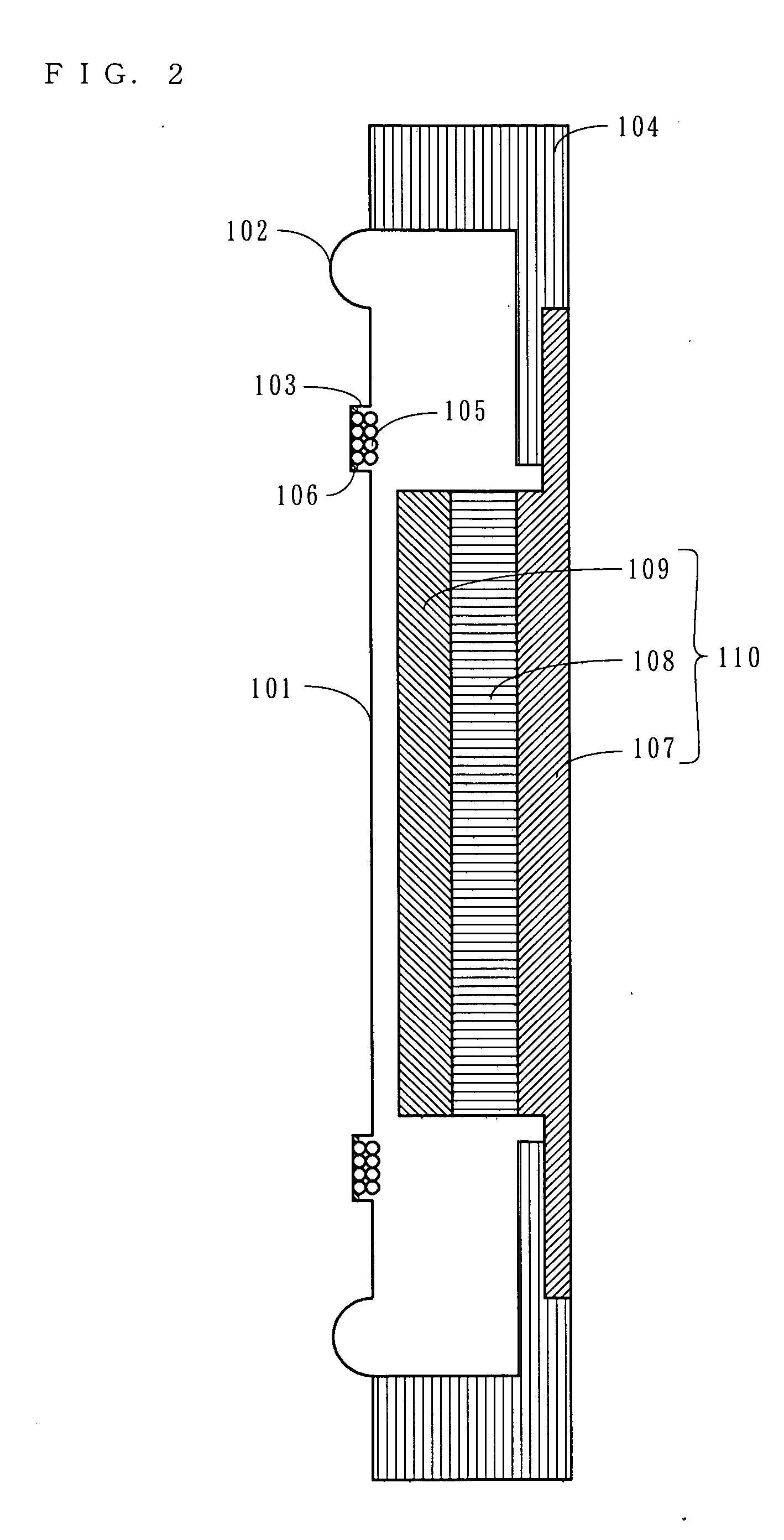
[0048] A loudspeaker according to a first embodiment of the present invention is now described. FIG. 1 is a plan view of the loudspeaker, FIG. 2 is a cross-sectional view (an A-B cross-sectional view) of the loudspeaker in a long axis direction, and FIG. 3 is a cross-sectional view (a C-D cross-sectional view) of the loudspeaker in a short axis direction. In FIGS. 1 through 3, the loudspeaker includes a diaphragm 101, an edge 102, a frame 104, a voice coil 105, a yoke 107, a magnet 108, and a top plate 109. As shown in FIG. 1, the loudspeaker has a shape which is elongated in a vertical (or horizontal) direction. Note that in the following descriptions, a side of the loudspeaker on which the diaphragm 101 is provided (the left side in FIG. 2) is referred to as an “upper surface side”, and a side on which the yoke 107 is provided (the right side in FIG. 2) is referred to as a “lower surface side”. Also, a longitudinal direction of the diaphragm 101, which is...

Example

[0061] (Second Embodiment)

[0062] Described next is a loudspeaker according to a second embodiment. FIG. 5 is a cross-sectional view of the loudspeaker according to the second embodiment in the short axis direction. Note that the loudspeaker according to the second embodiment has an external appearance similar to that of the loudspeaker according to the first embodiment. A plan view of the loudspeaker is omitted since it is similar to FIG. 1. FIG. 5 corresponds to FIG. 3 in the first embodiment. Note that in FIG. 5, elements similar to those shown in FIGS. 1 through 3 are denoted by the same reference numerals. Hereinbelow, the loudspeaker according to the second embodiment is described mainly with respect to differences from the loudspeaker according to the first embodiment.

[0063] In the second embodiment, as in the first embodiment, the voice coil 105 is bonded to the bottom of the groove 103 of the diaphragm 101. Here, in the second embodiment, an adhesive 201 is applied so as t...

Example

[0064] (Third Embodiment)

[0065] Described next is a loudspeaker according to a third embodiment. FIGS. 6 and 7 are views showing a loudspeaker of a third embodiment. Specifically, FIG. 6 is a plan view of the loudspeaker, and FIG. 7 is a cross-sectional view (an E-F cross-sectional view) of the loudspeaker in the short axis direction. Note that in FIGS. 6 and 7, elements similar to those shown in FIGS. 1 through 3 are denoted by the same reference numerals. Hereinbelow, the loudspeaker according to the third embodiment is described mainly with respect to differences from the loudspeaker according to the first embodiment.

[0066] In the third embodiment, a plurality of protrusions 301 are provided on the bottom of the groove 103 of the diaphragm 101. It is preferred that the protrusions 301 each are smaller (in height or width) than a diameter of a wire of the voice coil 105. The protrusions 301 may be regularly or irregularly placed on the bottom of the groove 103. Also, the protrus...


PUM


Abstract

A loudspeaker includes a diaphragm, an edge, and a voice coil. The diaphragm includes a groove having a concave cross section. Also, the diaphragm is in a horizontally or vertically elongated shape. The edge is coupled to an outer circumference of the diaphragm, and has a roughly half-round shaped cross section. The voice coil is bonded to the groove. The voice coil is thicker than a depth of the groove. Also, the voice coil has a cross section in which a dimension in a direction along a plane of the diaphragm is longer than a dimension in a direction perpendicular to the plane of the diaphragm.

Description

BACKGROUND OF THE INVENTION [0001] 1. Field of the Invention [0002] The present invention relates to a loudspeaker, and more particularly to a loudspeaker for use in a variety of types of audio apparatuses, for example, an audio and visual apparatus. [0003] 2. Description of the Background Art [0004] Conventionally, an audio and visual apparatus, such as a television, is configured so as to include loudspeakers on opposite sides of a cathode-ray tube. Accordingly, as the loudspeakers for use in the audio and visual apparatus, loudspeakers structured in an elongated shape, such as a rectangle, an ellipse, etc., are used. In recent years, as a display screen becomes wider, the loudspeakers for use in the audio and visual apparatus are required to become narrower, and also required to become thinner so as to be adapted to an apparatus with a thin depth, such as a liquid crystal display or a plasma display. [0005] Here, a conventional loudspeaker with an elongated structure is described...

Claims


Application Information

Patent Timeline
IPC IPC(8): H04R9/02H04R1/00H04R9/04H04R9/06
CPCH04R9/04H04R9/045H04R2307/025H04R7/04H04R2307/021H04R9/06H04R1/00H04R9/02
Inventor TAKEWA, HIROYUKIIWASA, MIKIOINABA, ATSUSHIKOURA, SATOSHI
Owner PANASONIC CORP
Why Eureka
Try Eureka