Wireless optical system

a wireless optical system and optical communication technology, applied in electromagnetic transmission, electrical equipment, transmission, etc., can solve the problems of increasing the number of received inputs, difficulty in applying optical communication techniques to mobile equipment, and difficulty in maintaining connection with slave devices, so as to achieve significant miniaturization of movable sections, increase the quantity of light entering the receiving element, and reduce the effect of slave device maintenan

Inactive Publication Date: 2005-02-24
FUJIFILM BUSINESS INNOVATION CORP
View PDF7 Cites 16 Cited by
  • Summary
  • Abstract
  • Description
  • Claims
  • Application Information

AI Technical Summary

Benefits of technology

[0018] According to the wireless optical system and system of the present invention, a transmitting section or a receiving section scans only a light-emitting element or a light-detecting element relative to a condenser lens, thereby enabling significant miniaturization of a movable section. The wireless optical system and system can be significantly miniaturized, and high-speed scanning also becomes possible. Moreover, by means of scanning of the light-emitting element and the light-detecting element, the quantity of light entering the receiving element can be increased, whereby transmission and reception can be performed with low power consumption. Accordingly, the wireless optical system can be applied to mobile equipment.

Problems solved by technology

For these reasons, an increase in a received input is required, and realization of efficient transmission / reception has arisen as a challenge to be met.
Moreover, when the slave device is moved, maintenance of connection with the slave device is difficult.
Thus, difficulty is encountered in applying the optical communication technique to the mobile equipment.
However, according to the related-art optical wireless system, when the slave device moves, difficulty is encountered in maintaining connection with the master device.
A device and signal processing become complicated.
Therefore, there has been a problem of difficulty in using the optical wireless system for mobile equipment.
Thus, there is a problem of the uploading speed of a signal from the slave device decreasing in inverse proportion to the number of slave devices.
Further, according to the related-art optical wireless system, in which the transmission element and the receiving element, the elements having different condenser lenses, are disposed side by side on a single holder and orientation of the system is two-dimensionally adjusted by means of rotation of the motor attached to the holder, the slave device assumes a size of about 10 cm or more, and power consumption becomes very large, on the order of 2 watts or thereabouts.
Therefore, there arises a problem of difficulty in employing the optical wireless system for mobile equipment.

Method used


Image

  • Wireless optical system
  • Wireless optical system
  • Wireless optical system

Examples


first embodiment

[0036] (First Embodiment)

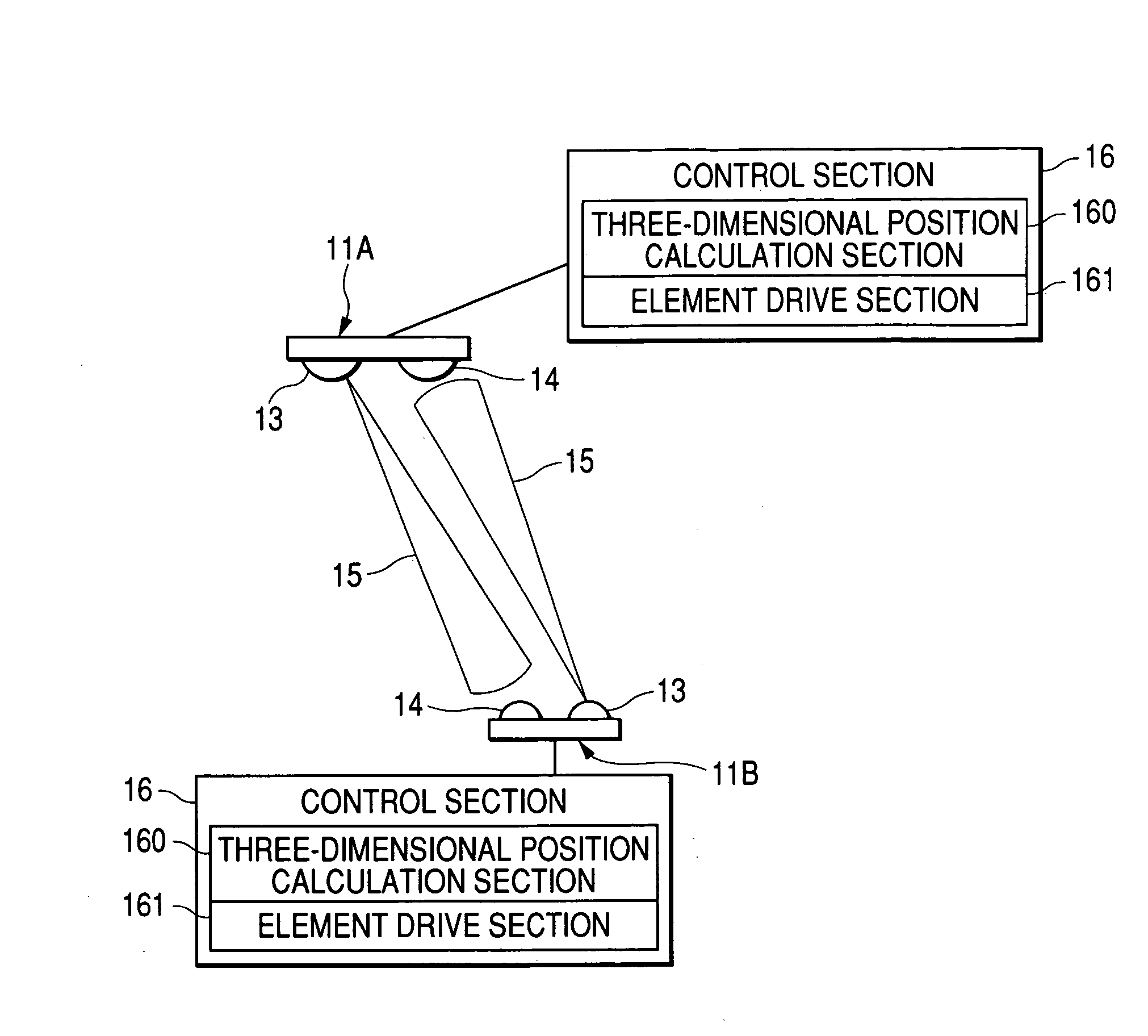
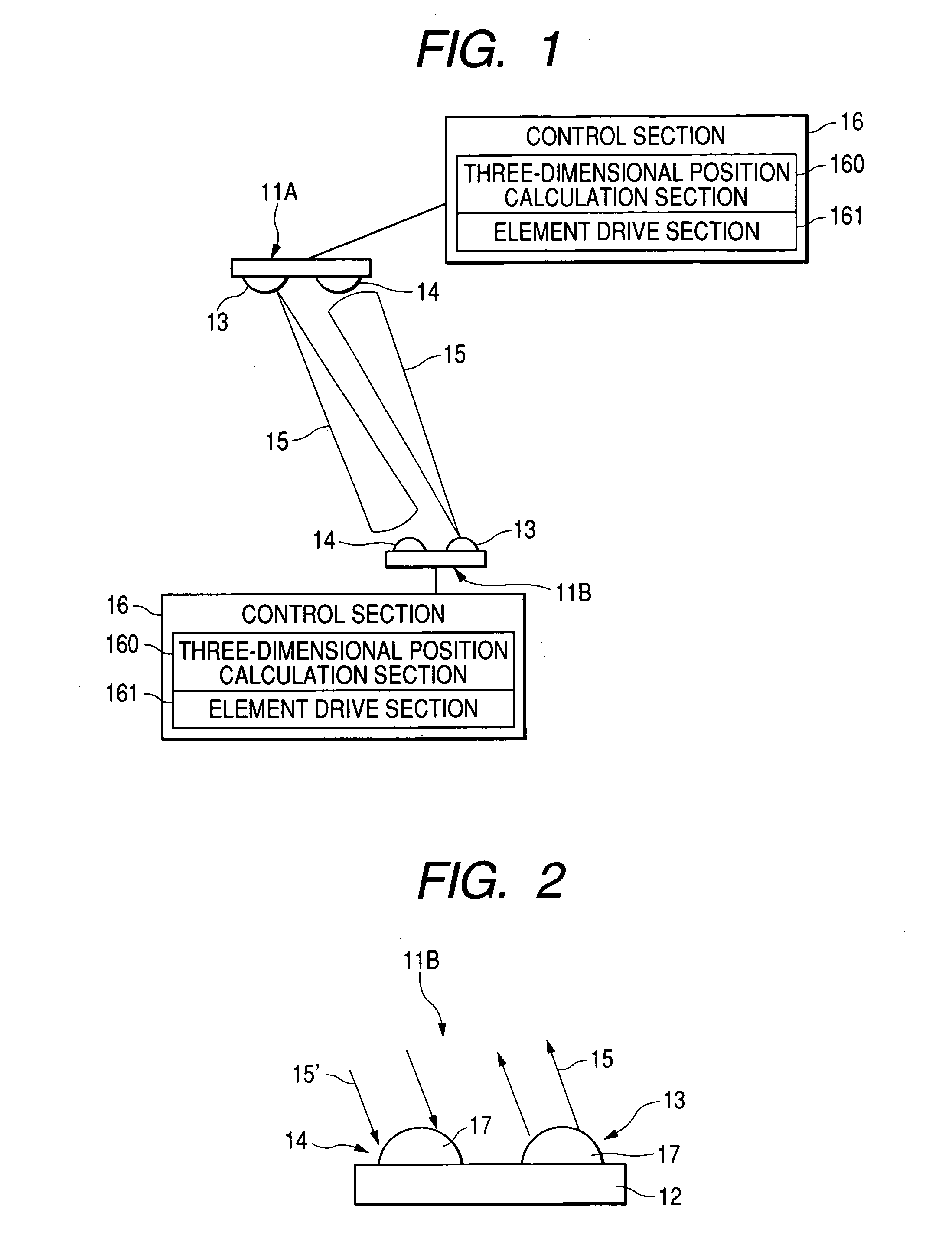
[0037]FIG. 1 shows an optical wireless system according to a first embodiment of the invention. The optical wireless system of the first embodiment transmits and receives an information signal between a master device 11A serving as an optical wireless device and a slave device 11B serving as another optical wireless device. The master device 11A and the slave device 11B have identical configurations. They are respectively configured to have a transmitting section 13, a receiving section 14, and a control section 16 including a three-dimensional position calculation section 160 for calculating a three-dimensional position of the transmitting section 13 of the master device 11A or the slave device 11B on the other end and an element drive section 161 for driving an MEMS (Micro Electro-Mechanical System) element to be described later.

[0038] As shown in FIG. 1, at the time of initiation of transmission and reception, the master device 11A transmits transmission...

second embodiment

[0049] (Second Embodiment)

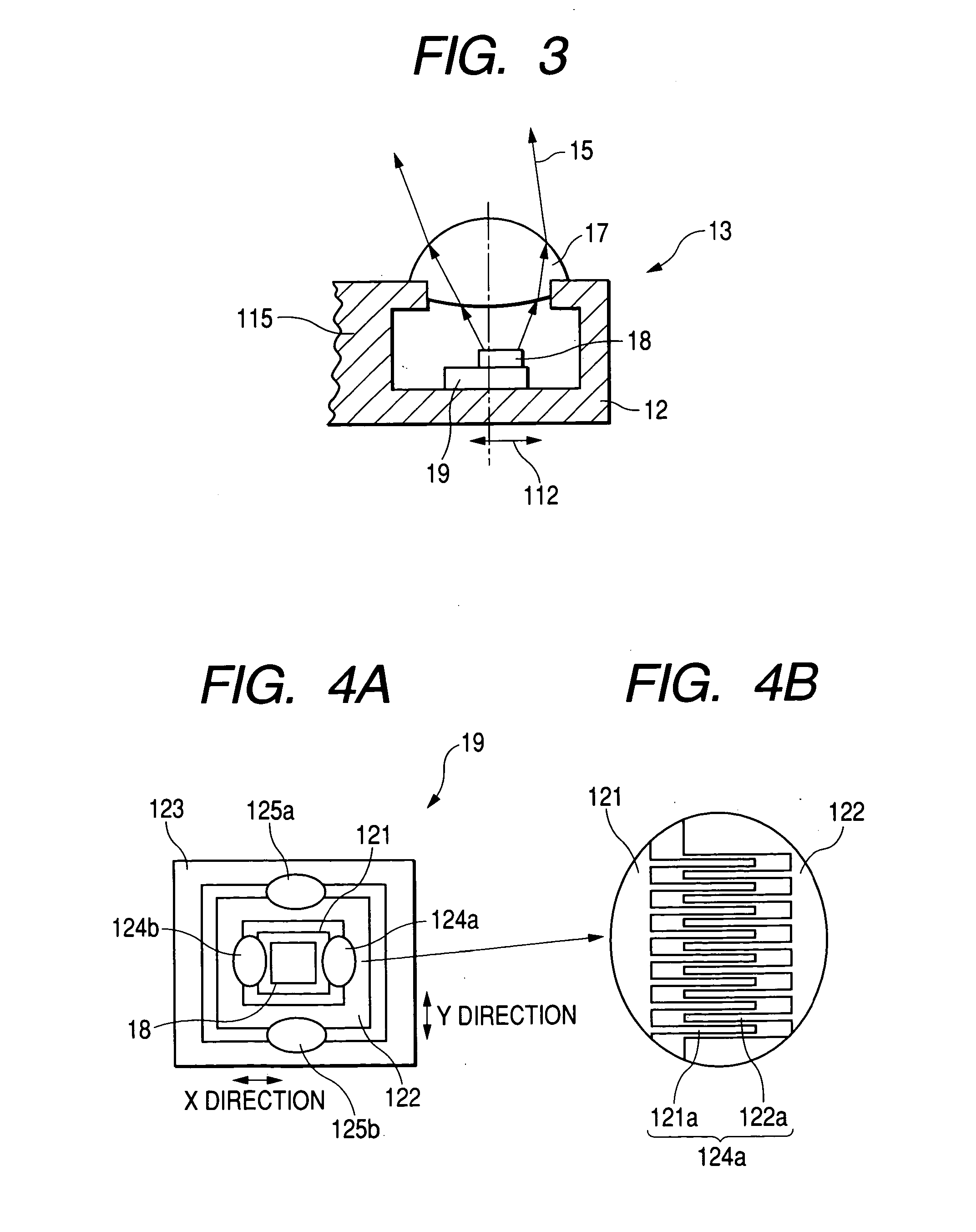
[0050]FIG. 7 shows the receiving section 14 of the slave device 11B according to a second embodiment of the present invention. As shown in FIG. 7, the receiving section 14 differs from the transmitting section 13 shown in FIG. 3 only in that the light-emitting element 18 is replaced with the light-detecting element 116. In other respects, the receiving section 14 is configured in the same manner as is the transmitting section 13. The light-detecting element 116 is disposed in the vicinity of the focal point of the condenser lens 17, and the single pin photodiode 117 is stacked on the MEMS element 19. The MEMS element 19 scans the light-detecting element 116 in directions 112 within two dimensions.

[0051] The size of the pin photodiode 117 is made substantially equal to the diameter of the optical spot 118 converted by the condenser lens 17. The position of the pin photodiode 117 is two-dimensionally wobbled, and the intensity of the received light 15′ is sy...

third embodiment

[0053] (Third Embodiment)

[0054]FIG. 8 shows an optical wireless device according to a third embodiment of the present invention. The third embodiment is based on the first embodiment, wherein the light-emitting element 18 and the light-detecting element 116 are disposed in the vicinity of the condenser lens 17 so as to transmit and receive by way of a common beam splitter 119 and the common condenser lens 17. According to the third embodiment, the position of the light-emitting element 18 and that of the light-detecting element 116 are scanned with respect to the common condenser lens 17. The transmitting section and the receiving section are assembled into a single unit such that transmission is performed by controlling the transmitting and reception directions and the directional angle. As a result, the optical wireless device can be made compact to a much greater extent.

[0055] The present invention is not limited to the first to third embodiments set forth and is susceptible to ...


PUM


Abstract

A master device and a slave device are each constituted of a transmitting section; a receiving section; and a control section including a three-dimensional position calculation section for calculating a three-dimensional position of the transmitting section of the counterpart master device or that of the counterpart slave device and an element drive section for driving an MEMS element. First, the master device outputs transmission light having comparatively narrow directivity, and the transmission light is two-dimensionally scanned. Next, the receiving section of the slave device receives that transmission light, calculates the transmission direction of the master device from the position of a spot of transmitted light on a light-detecting element array, and transmits the transmission light in that direction. At this point in time, scanning of the transmission light from the master device is stopped, and subsequently communication is initiated.

Description

BACKGROUND OF THE INVENTION [0001] 1. Field of the Invention [0002] The present invention relates to a wireless optical system which transmits and receives an information signal to and from a device in communication therewith, as well as to a wireless optical system which transmits and receives an information signal between a master device and a slave device. More particularly, the present invention relates to the wireless optical system and the wireless optical system which attempt to attain compactness and low power consumption and can be applied to a mobile equipment. [0003] 2. Description of the Related Art [0004] Like radio communication, optical wireless communication does not require any wiring, and, unlike radio communication, optical wireless communication comparatively readily enables high-speed communication at 100 Mbps or higher. Therefore, optical wireless communication is considered a potential technique for linking a LAN with fixed or semi-fixed equipment, such as a p...

Claims


Application Information

Patent Timeline
Patent Type & Authority Applications(United States)
IPC IPC(8): H04B10/10
CPCH04B10/1149
Inventor UEYANAGI, KIICHIADACHI, YUKIOSEKO, YASUJIHOTTA, HIROYUKIOZAWA, TAKASHI
Owner FUJIFILM BUSINESS INNOVATION CORP
Why Eureka
Try Eureka