
Method for operating a wind park

a technology of wind power and wind power, applied in the direction of wind power generation, emergency protective arrangements for automatic disconnection, liquid fuel engine components, etc., can solve the problems of no longer being able to set up further wind power installations at such sites, network frequency rises very quickly and abruptly, damage to electrical machines, etc., and achieves simple effect of different throttling and easy adaptation

Inactive Publication Date: 2005-02-24
WOBBEN ALOYS
View PDF23 Cites 87 Cited by
  • Summary
  • Abstract
  • Description
  • Claims
  • Application Information

AI Technical Summary

Benefits of technology

"The invention proposes a solution for regulating the power output of a wind park to ensure that it always stays within the limits set by the network. This allows for better utilization of the wind park and better balancing of network components. The wind park can produce more power than the network can handle, so the regulation system comes into play to limit the power output to a maximum value. The regulation can be done based on the data input of each installation or the network voltage. The invention also allows for individual or all wind power installations to be throttled, resulting in higher energy yield from the wind park. The wind park management can be easily adapted to the situation and temporary stops of individual or multiple installations can be accommodated. The invention provides a solution for regulating the power output of a wind park to maximize energy yield while ensuring that the network is always being utilized optimally."

Problems solved by technology

It is precisely there that the technical connection limits are quickly reached by the wind power installations, with the result that it is then no longer possible for further wind power installations to be set up at such sites.
Another issue is that in the case of low-power electrical networks, some of which are called island networks, the network frequency rises very quickly and abruptly if a relatively large consumer is separated from the electrical network.
As many electrical devices, for example computers, electric motors and the like, which are connected to the electrical network, are however not designed for fluctuating network frequencies or abrupt changes therein, that can result in damage to electrical machines, even going as far as destruction thereof.

Method used


Image

  • Method for operating a wind park
  • Method for operating a wind park
  • Method for operating a wind park

Examples


Embodiment Construction

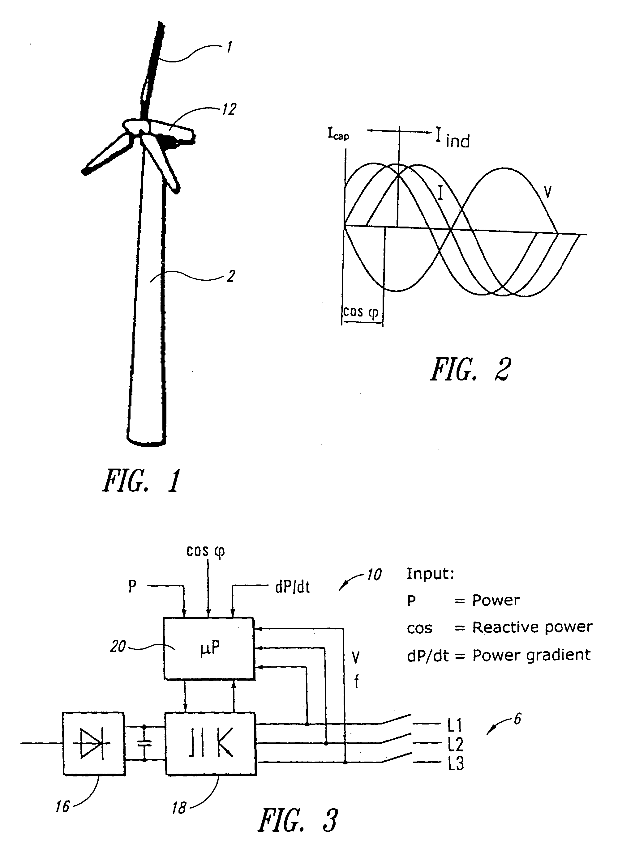
[0034]FIG. 1 shows a wind power installation 2 having rotor blades 1 coupled to a rotor shaft that drives a generator 12.

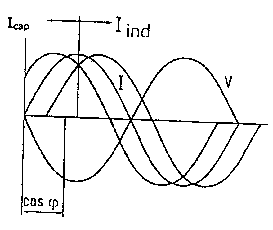
[0035]FIG. 2 shows changes that can be made to the power factor to adjust the total power delivered to the network.

[0036]FIG. 3 is a block circuit diagram showing the control system 10 of a wind power installation. It includes a microprocessor μP 20 connected to an inverter apparatus 18 (PWR), by means of which multi-phase alternating current can be fed into the power supply network 6. The microprocessor has a power input P, an input for inputting a power factor, cos phi (cos φ) and an input for inputting the power gradient (dP / dt).

[0037] The inverter apparatus comprising a rectifier, a rectifier intermediate circuit and an inverter is connected to the generator of a wind power installation and receives therefrom the energy produced by the generator, in rotary speed-variable fashion, that is to say, in dependence on the rotary speed of the rotor of the wind pow...


PUM


Abstract

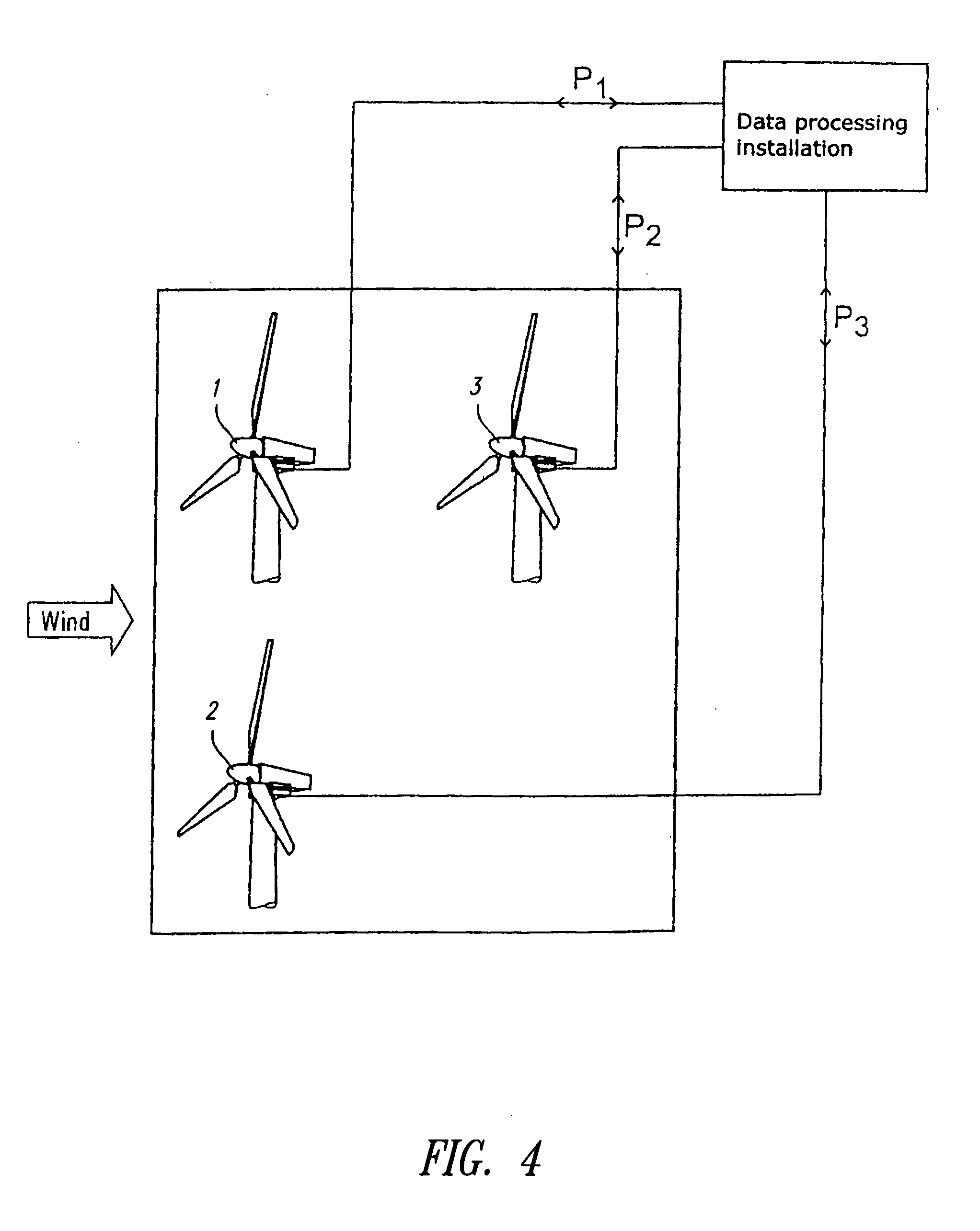
Wind power installations were initially always erected in the form of individual units and it is only in recent years that, caused also by administrative and building regulations, wind power installations are frequently installed in wind parks. In that respect a wind park in its smallest unit is an arrangement of at least two wind power installations, but frequently markedly more. By way of example mention may be made of the wind park at Holtriem (East Frisia) where more than 50 wind power installations are set up in an array. It is to be expected that the number of units and also the installed power of the wind power installations will also increase greatly in the forthcoming years. In most cases the wind potential is at its greatest in regions of the power supply networks with a low level of short-circuit power and low population density. It is precisely there that the technical connection limits are quickly reached by the wind power installations, with the result that it is then no longer possible for further wind power installations to be set up at such sites._A method of operating a wind park comprising a plurality of wind power installations, wherein the wind park is connected to an electrical power supply network into which the electrical power produced by the wind park is fed and the wind park and / or at least one of the wind power installations of the wind park has a control input, by means of which the electrical power of the wind park or one or more individual wind power installation or installations can be set in a range of between 0 and 100% of the respective power to be made available, in particular the nominal power, and that there is provided a data processing apparatus which is connected to the control input and by means of which the setting value is set in the range of between 0 and 100%, depending on how great is the power that the overall wind park provides at its output for feeding into the energy network and wherein the operator (PSU) of the electrical supply network to which the wind park is connected can adjust the power delivered by the wind park by way of the control input.

Description

BACKGROUND OF THE INVENTION [0001] 1. Field of the Invention [0002] The invention concerns a method of operating a wind park and also a wind park as such. [0003] 2. Description of the Related Art [0004] Wind power installations were initially always erected in the form of individual units and it is only in recent years that, caused also by administrative and building regulations, wind power installations are frequently installed in wind parks. In that respect a wind park in its smallest unit is an arrangement of at least two wind power installations, but frequently markedly more. By way of example mention may be made of the wind park at Holtriem (East Frisia) where more than 50 wind power installations are set up in an array. It is to be expected that the number of units and also the installed power of the wind power installations will also increase greatly in the forthcoming years. In most cases the wind potential is at its greatest in regions of the power supply networks with a lo...

Claims


Application Information

Patent Timeline
Patent Type & Authority Applications(United States)
IPC IPC(8): B63H1/06F03D7/02F03D7/00F03D7/04H02J3/38H02P9/00
CPCF03D7/0272F03D7/0284F03D7/048F03D9/003F05B2270/1033F05B2270/304H02J3/386F05B2270/337Y02B10/30Y02E10/723Y02E10/725Y02E10/763F05B2270/335F03D9/255F03D9/257H02J2300/28H02J3/381Y02E10/76Y02E10/72H02J3/40H02J3/38
Inventor WOBBEN, ALOYS
Owner WOBBEN ALOYS
Learn More