
Insulation system having vacuum encased honeycomb offset panels

a technology of offset panels and honeycombs, which is applied in the field of high thermal resistive materials, can solve the problems of increasing the weight of the panel, inability to meet the requirements of many applications, and the material used to provide insulation is considered to have an insignificant structural value, etc., and achieves high thermal resistance and strength.

Inactive Publication Date: 2005-02-24
BOARD OF TRUSTEES OF UA FOR & ON BEHALF OF UAH
View PDF11 Cites 50 Cited by
  • Summary
  • Abstract
  • Description
  • Claims
  • Application Information

AI Technical Summary

Benefits of technology

[0010] Embodiments of the present invention provide an insulation system having high thermal resistance and strength.
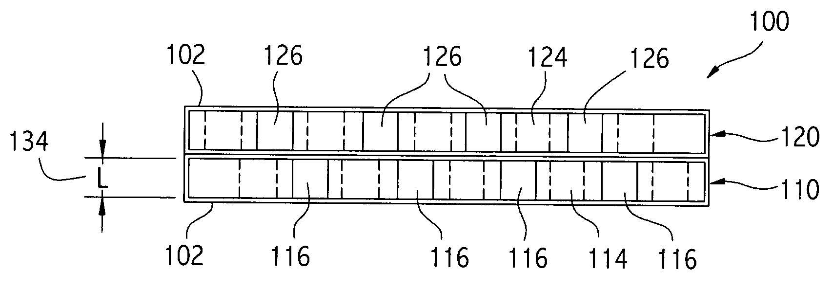
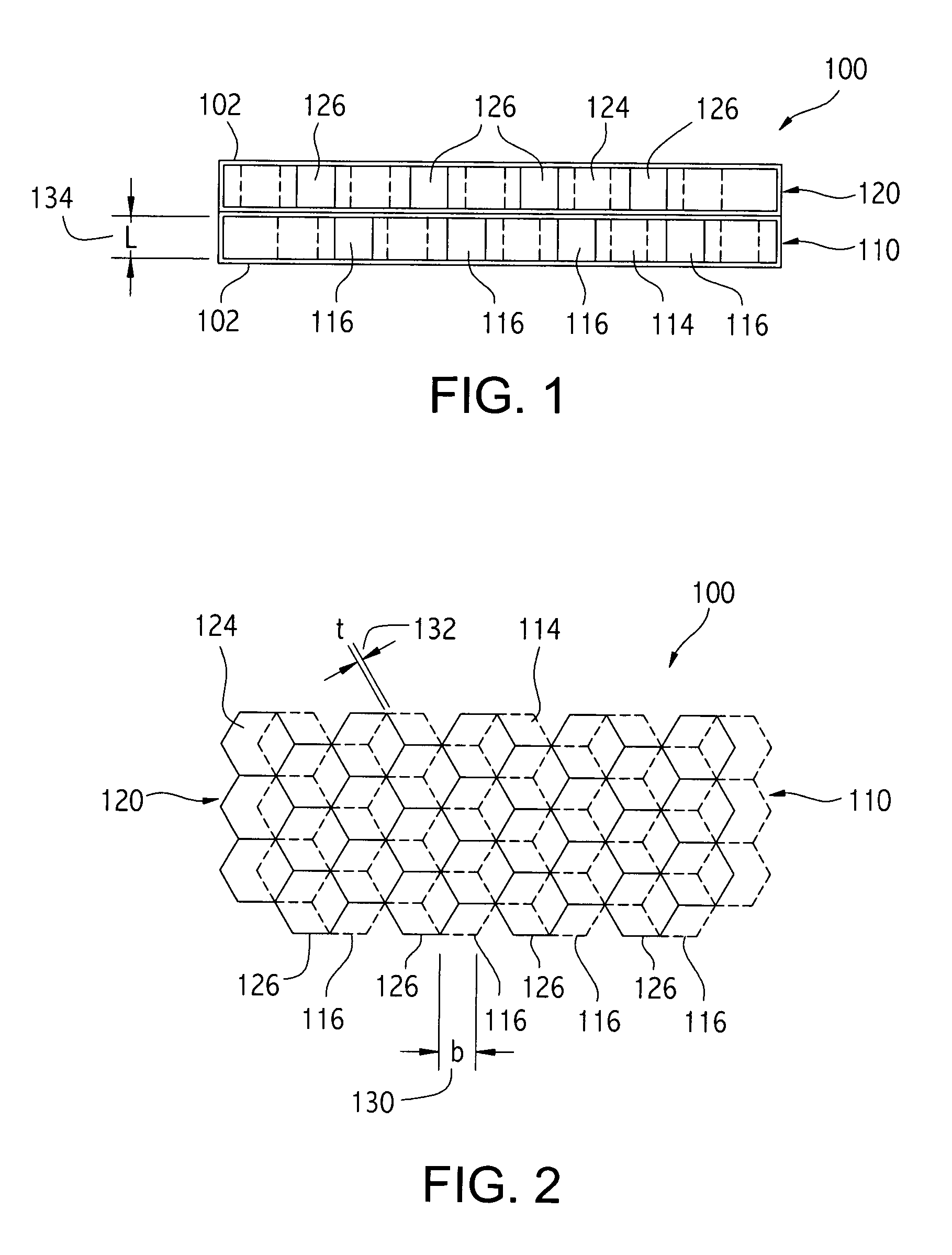
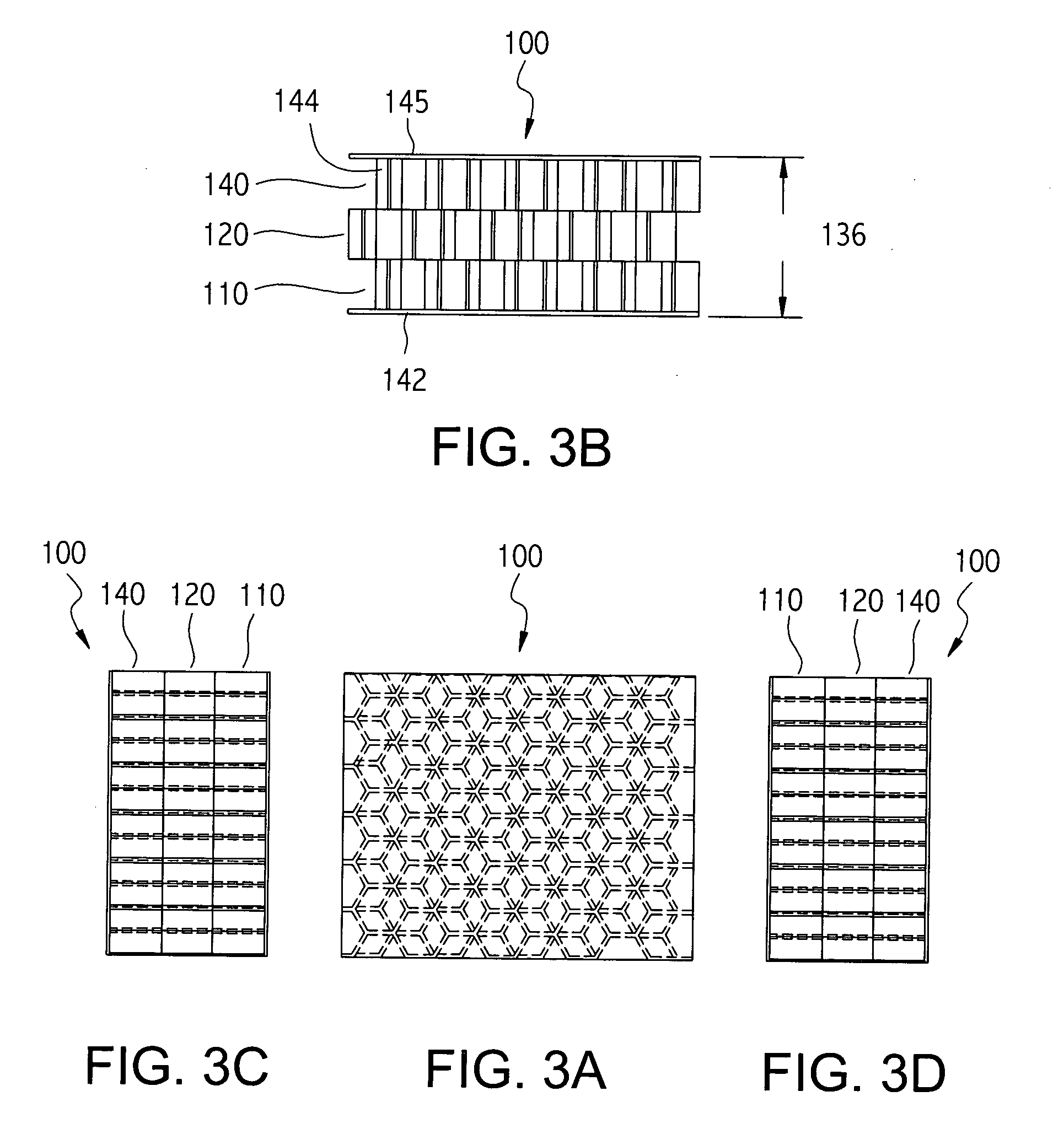
[0011] In a first embodiment an insulation system comprises a first honeycomb core encased in an evacuated container of insulating material. A second honeycomb panel having a honeycomb core is encased in an evacuated container of insulating material and then the first and second honeycomb panels are secured together in an offset arrangement in order to minimize the contact between the edges of the honeycomb cores. Additional encased and vacuumed honeycomb core panels may be layered with the first and second honeycomb panels to further reduce the thermal conductivity and provide an insulation system that compares favorably with the best known insulation materials. The insulation system of the present invention has excellent strength characteristics and has a greater thermal resistance than conventional insulation system materials having approximately the same strength characteristics.

Problems solved by technology

However, the materials used to provide insulation are considered to have an insignificant structural value.
Although there is an interaction between the structural and thermal designers, the structure and the thermal control considerations are generally not approached as an integral design effort.
Although the high thermal resistance materials contained in the cells significantly improve the insulation characteristics of the honeycomb panels, the weight of the panel is increased and the cost may be unacceptable for many applications.
Although the strength and stiffness of honeycomb cores are desirable structural characteristics, the conventional techniques for increasing the thermal resistance of honeycombs do not typically provide a panel with both desirable thermal and strength characteristics.
Thus, a heretofore unaddressed need exists in the industry to address the aforementioned deficiencies and inadequacies.

Method used


Image

  • Insulation system having vacuum encased honeycomb offset panels
  • Insulation system having vacuum encased honeycomb offset panels
  • Insulation system having vacuum encased honeycomb offset panels

Examples


Embodiment Construction

[0023] Several embodiments of an insulation system herein utilize the idea that several layers or stacks of honeycomb panels having cells of adjacent honeycomb cores that are offset, so as to reduce the area of contact, significantly reduces conduction heat transfer and hence increases the thermal resistance between the honeycomb panels. In addition, the total thermal resistance of an insulation system can be further increased by encasing and sealing each of the honeycomb cores within multiple layers of a radiation barrier material, such as aluminized mylar, thereby providing a sealed enclosure. To reduce convective heat transfer, increasing the thermal resistance even more, the interior of the sealed enclosure can be evacuated to provide a vacuum environment so that convective heat transfer within the honeycomb cells is negligible. Manufacturers of honeycomb cores, the structural element of honeycomb panels, have indicated that one way to improve the insulation properties of honeyc...


PUM

PropertyMeasurementUnit
temperatureaaaaaaaaaa
pressureaaaaaaaaaa
thickaaaaaaaaaa

Abstract

An insulation system comprising layers of honeycomb cores where each core is enclosed in a sealed container made of radiation barrier material. The container is evacuated and becomes a vacuum enclosure for the honeycomb cores. To reduce the heat transfer between the honeycomb cores, the cores are placed in an offset arrangement.

Description

STATEMENT REGARDING FEDERALLY SPONSORED RESEARCH OR DEVELOPMENT [0001] The U.S. government has a paid-up license in this invention and the right in limited circumstances to require the patent owner to license others as provided for by the terms of NASA cooperative agreement no. NCC8-132.TECHNICAL FIELD [0002] The present invention is generally related to high thermal resistive materials, and, more particularly, is related to layers of honeycomb cores that are positioned in an offset arrangement and encased in a vacuum enclosure of radiation barrier material. BACKGROUND OF THE INVENTION [0003] Panels that have a high thermal resistance are useful as insulators for a variety of applications and products. For example, containers utilizing thermal energy phase change material for keeping temperature sensitive materials, such as food and medicine, within a given temperature range can use such panels to significantly increase storage time. Additional product areas where high thermal resis...

Claims


Application Information

Patent Timeline
Patent Type & Authority Applications(United States)
IPC IPC(8): B32B3/12B32B15/08F16L59/065F16L59/07
CPCB32B3/12B32B15/08Y10T428/24149F16L59/07F16L59/065B32B3/06B32B15/09B32B27/36B32B2307/206
Inventor BLACKMON, JAMES B.WESSLING, FRANCIS C.
Owner BOARD OF TRUSTEES OF UA FOR & ON BEHALF OF UAH
Learn More