
Network camera

Active Publication Date: 2005-02-24
SONY CORP
View PDF11 Cites 27 Cited by
  • Summary
  • Abstract
  • Description
  • Claims
  • Application Information

AI Technical Summary

Benefits of technology

[0011] Still another object of the present invention is to effectively utilize the life of a memory, even when a recording medium, such as a flash memory having reduced number of times of data writing is used as a backup memory.
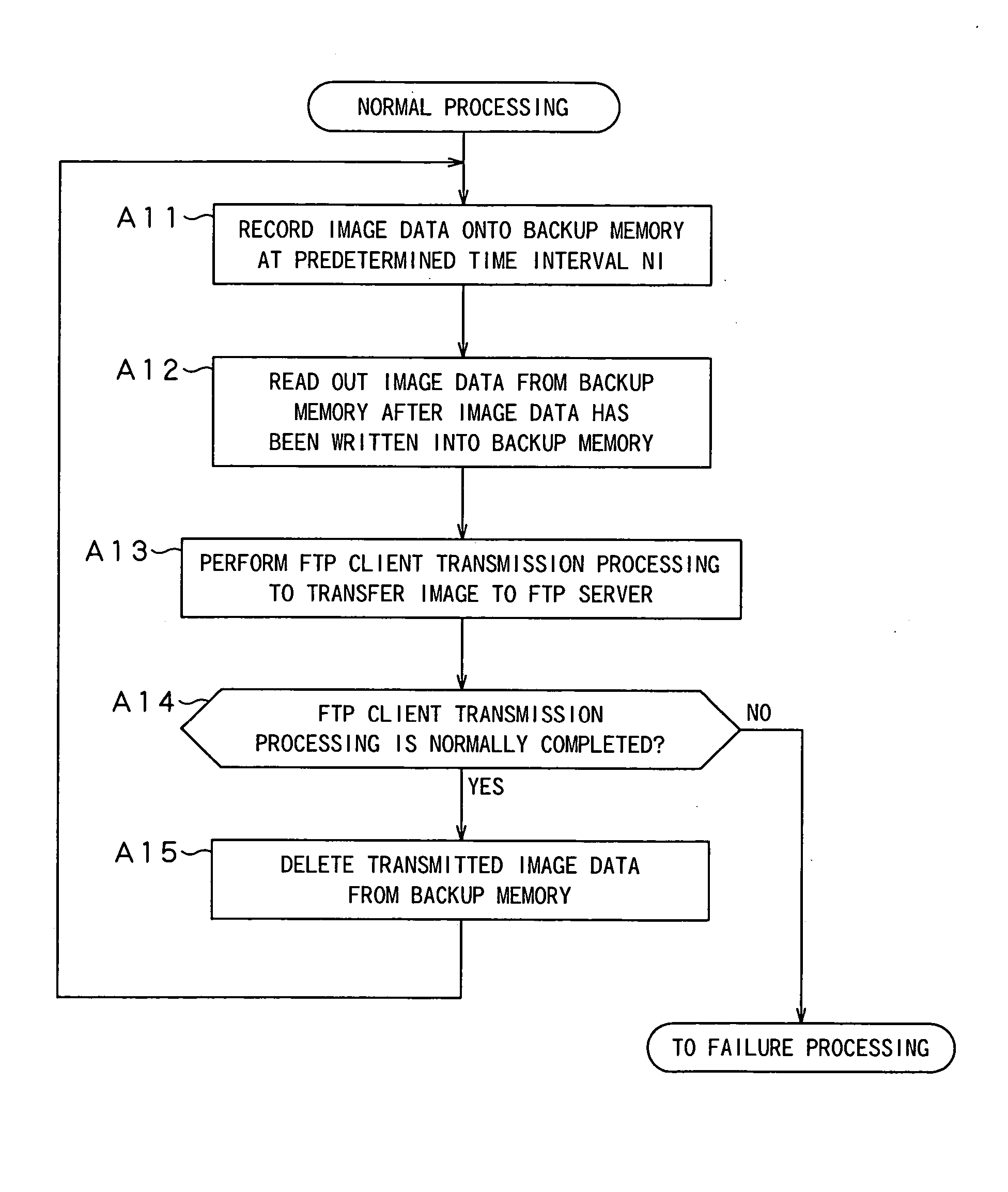
[0016] With the above configuration, even when a network line is temporarily out of service, a network camera according to the present invention can back up image data during the network breakdown on a memory thereof and transmit the backed up image data to a server after the network line has recovered.
[0018] Further, by individually setting a transmission time interval during normal time and a transmission time interval at the time of occurrence of backup data, load on the FTP server and bandwidth used in the network line can adequately be controlled.
[0019] Further, image data is backed up on a backup memory unit only during network breakdown, thereby maximizing the use of the life of a memory when a recording medium, such as a flash memory having reduced number of times of data writing is used as a backup memory.

Problems solved by technology

There is a possibility that a network for data transfer is temporarily out of service for many reasons.
It is known that ADSL transmission, which has become increasingly widespread in recent years, is weak against electromagnetic noise, and accordingly, a line fault frequently occurs depending on the installation environment.
Further, a network is constructed and managed by various kinds of equipments, and there is also a case where a network line is out of service due to maintenance of these equipments.
When the network breakdown occurs in a conventional FTP client / server system, the image data being transferred during this breakdown time is treated as send error, with the result that the image data will not be transmitted to the FTP server.
A loss of the required image data is a serious problem in a security monitoring system, which poses a major obstruction to an introduction of the network camera to a security system.

Method used


Image

  • Network camera
  • Network camera
  • Network camera

Examples


Embodiment Construction

[0030] An embodiment of the present invention will be described in detail with reference to the accompanying drawings.

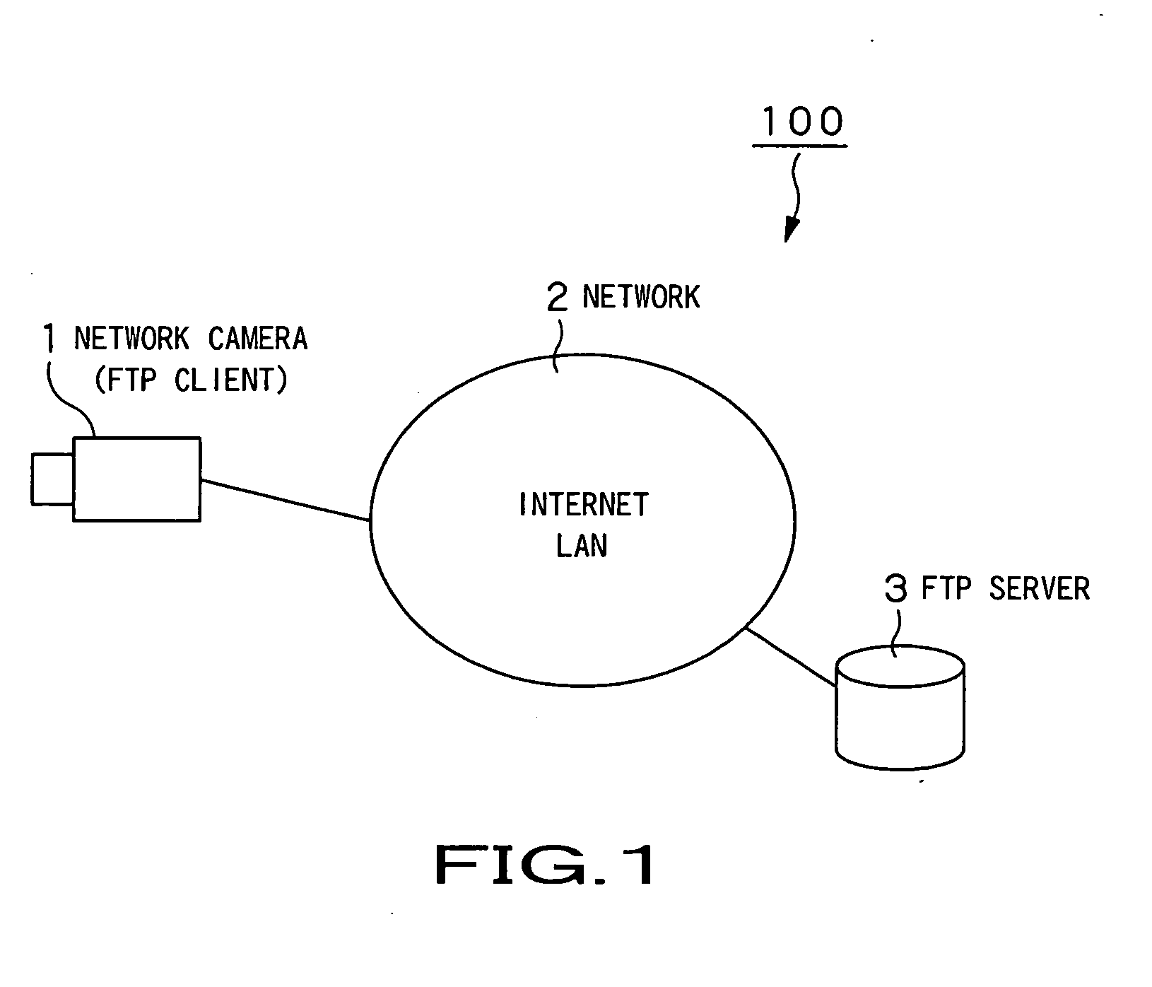
[0031] The present invention is applied to a client / server system 100 having a configuration as shown in, for example, FIG. 1.

[0032] The client / server system 100 is an FTP (File Transfer Protocol) client / server system configured to upload real-time image data obtained by a network camera 1 connected to a network 2 such as the Internet or a LAN to a server 3 connected to the same network 2 using FTP. More specifically, the client / server system 100 is used for, for example, a monitoring system or real-time monitoring system in which the network camera 1 serving as an FTP client on the network 2 uploads image data to the FTP server 3 on the same network 2.

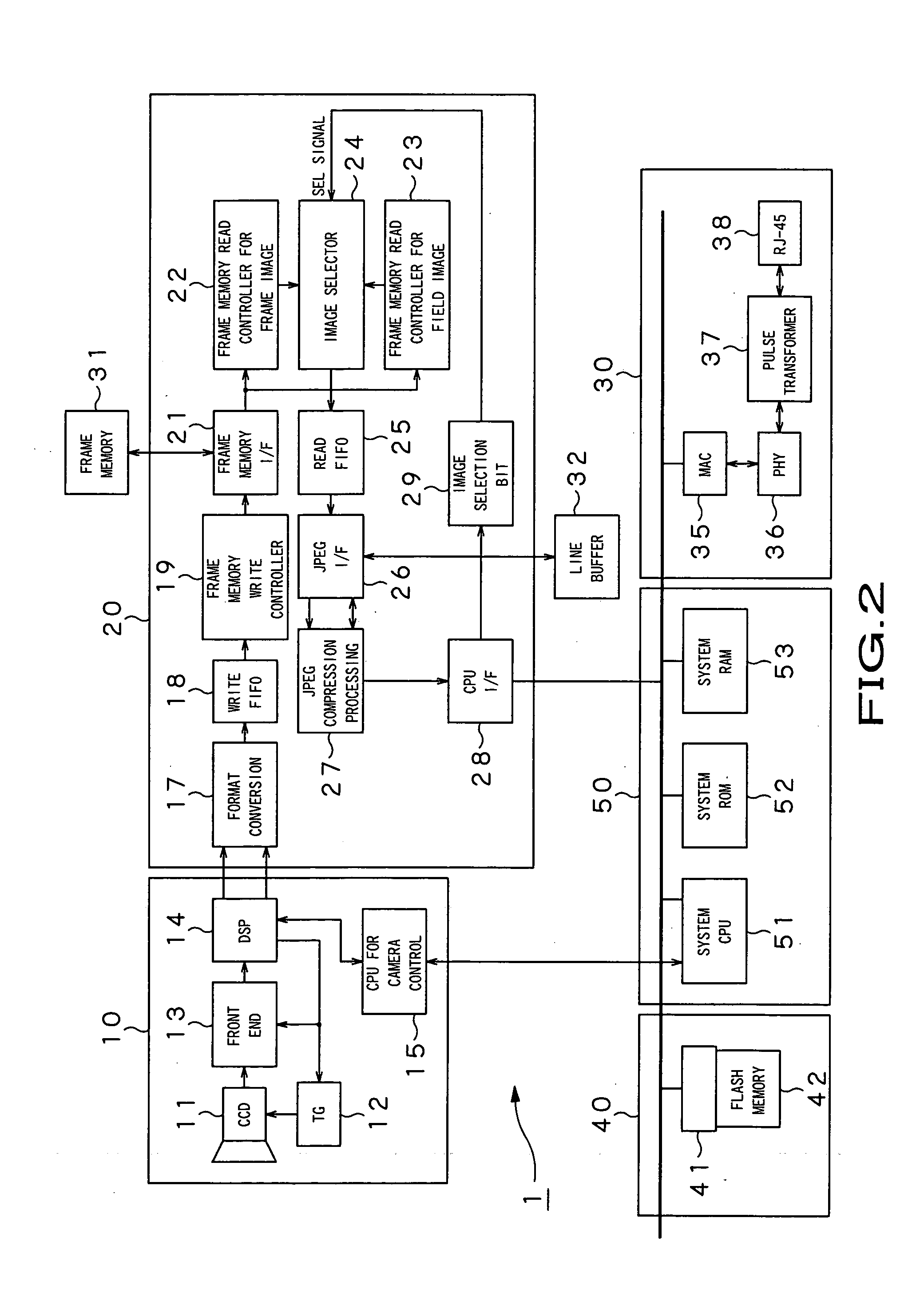
[0033] As shown in FIG. 2, the network camera 1 comprises a camera block 10 for taking an image, a signal processing unit 20 supplied with an imaging output of the camera block 10, a communication interface unit 30 ...


PUM


Abstract

A network camera 1 comprises a camera block 10 for taking an image, a signal processing unit 20 supplied with an imaging output of the camera block 10, a communication interface unit 30 which connects to an external network to establish communication, a backup memory unit 40 which temporarily stores data to be transmitted to an external device via the communication interface unit 30, a system control unit 50 which controls the above components, and the like. The system control unit 50 monitors the state of the network and stores temporarily the compressed image data to be transmitted to the server in the backup memory unit 40 when a failure occurs in the network, and controls transmission processing such that the compressed image data that has been stored in the backup memory unit 40 is transmitted to the server after the network has recovered.

Description

BACKGROUND OF THE INVENTION [0001] 1. Field of the Invention [0002] The present invention relates to a network camera which transmits image data in real time to a server connected thereto via a network such as the Internet. [0003] This application claims priority of Japanese Patent Application No.2003-188464 , filed in Japan on Jun. 30, 2003, the entirety of which is incorporated by reference herein. [0004] 2. Description of the Related Art [0005] In recent years, broadband environment such as an ADSL (Asymmetric Digital Subscriber Line) has become widespread, and a network camera has accordingly come into use, which allows, for example, viewing of the images that are transmitted, through the Internet, from the remotely located network camera on the screen of a personal computer or mobile phone, or viewing of the images transferred from the network camera located within a LAN (Local Area Network) installed in a factory or company on the screen of the personal computer. An image pick...

Claims


Application Information

Patent Timeline
IPC IPC(8): H04L69/40H04N5/76H04N5/765H04N5/225H04N7/18
CPCH04L29/06H04N5/23206H04N21/21805H04N21/4223H04L69/329H04L67/2861H04L67/2819H04L67/2842H04L69/40H04L67/06H04L67/564H04L67/568H04L67/59H04N23/661H04L9/40
Inventor NAKAMURA, MINORU
Owner SONY CORP
Learn More