
Multiple-contact woven electrical switches

a multi-contact, electrical switch technology, applied in the field of electrical switches, can solve the problems of inability to meet the needs of many applications, and large number of individual connectors,

Active Publication Date: 2005-03-03
METHODE ELETRONICS INC
View PDF80 Cites 53 Cited by
  • Summary
  • Abstract
  • Description
  • Claims
  • Application Information

AI Technical Summary

Benefits of technology

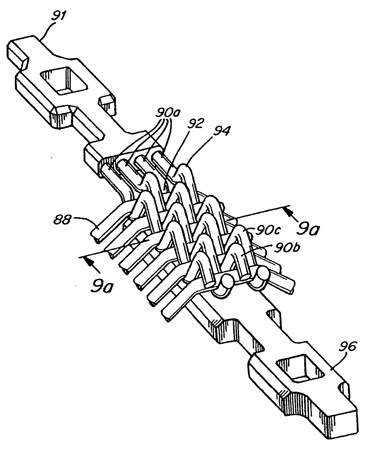
[0019] In certain embodiments, a plurality of loading fibers can be arranged to form a grid having a plurality of intersections. The conductors can be woven onto one or more of the loading fibers at or near an intersection of the grid.

Problems solved by technology

Regardless of the type of electrical system, advances in technology have led electronic circuits and components to become increasingly smaller and more powerful.
However, individual connectors are still, in general, relatively large compared to the sizes of circuit traces and components.
This may be undesirable in many applications, as will be discussed in more detail below.
Asperity interactions result from interference between surface irregularities as the surfaces slide over each other.
The breaking of these welds as the surfaces slide with respect to one another is a source of friction.
In addition, particles may become trapped between the contacting surfaces of the connector.
The groove 56 causes wear of the connector, and may be particularly undesirable in gold-plated connectors where, because gold is a relatively soft metal, the particle may plow through the gold-plating, exposing the underlying substrate of the connector.
This accelerates wear of the connector because the exposed connector substrate, which may be, for example, copper, can easily oxidize.
Oxidation can lead to more wear of the connector due to the presence of oxidized particles, which are very abrasive.
In addition, oxidation leads to degradation in the electrical contact over time, even if the connector is not removed and re-inserted.
However, a disadvantage of these conventional particle traps is that it is significantly more difficult to machine surface 64 with traps than without, which adds to the cost of the connector.
The particle traps also produce features that are prone to increased stress and fracture, and thus the connector is more likely to suffer a catastrophic failure than if there were no particle traps present.
Also, the contacts may have to open and close many times during its lifetime (over a million cycles is not uncommon) so contact friction and wear are important parameters.
If a large arc is produced, this can lead to contact damage.

Method used


Image

  • Multiple-contact woven electrical switches
  • Multiple-contact woven electrical switches
  • Multiple-contact woven electrical switches

Examples


Embodiment Construction

[0072] The present invention provides an electrical connector that may overcome the disadvantages of prior art connectors. The invention comprises an electrical connector capable of very high density and using only a relatively low normal force to engage a connector element with a mating connector element. It is to be understood that the invention is not limited in its application to the details of construction and the arrangement of components set forth in the following description or illustrated in the drawings. Other embodiments and manners of carrying out the invention are possible. Also, it is to be understood that the phraseology and terminology used herein is for the purpose of description and should not be regarded as limiting. The use of “including,”“comprising,” or “having” and variations thereof is meant to encompass the items listed thereafter and equivalents thereof as well as additional items. In addition, it is to be appreciated that the term “connector” as used herei...


PUM


Abstract

The present disclosure is directed to electrical switches that utilize conductors that are woven onto loading fibers and a mating conductor that has a contact mating surface. Each conductor has at least one contact point. The loading fibers are capable of delivering a contact force at each contact point of the conductors. Electrical connections are established between the contact points of conductors and the contact mating surface of the mating conductor when the conductor-loading fiber weave is engaged with the mating conductor and the electrical connections are terminated when the conductor-loading fiber weave is disengaged from the mating conductor. In one embodiment, the portion of the contact mating surface of the mating conductor where arcing between the conductors and the mating conductor is expected to occur is plated with a conductive arc-tolerant material, such as silver, for example. In another embodiments, the portions of the conductors where arcing is expected to occur are plated with a conductive arc-tolerant material. In an alternate embodiment, the conductors are made thicker where arcing between the conductors and the mating conductor is expected to occur. The contact mating surface of the mating conductor can include a non-conductive portion that assists in guiding the conductor-loading fiber weave when its being engaged and disengaged from the mating conductor.

Description

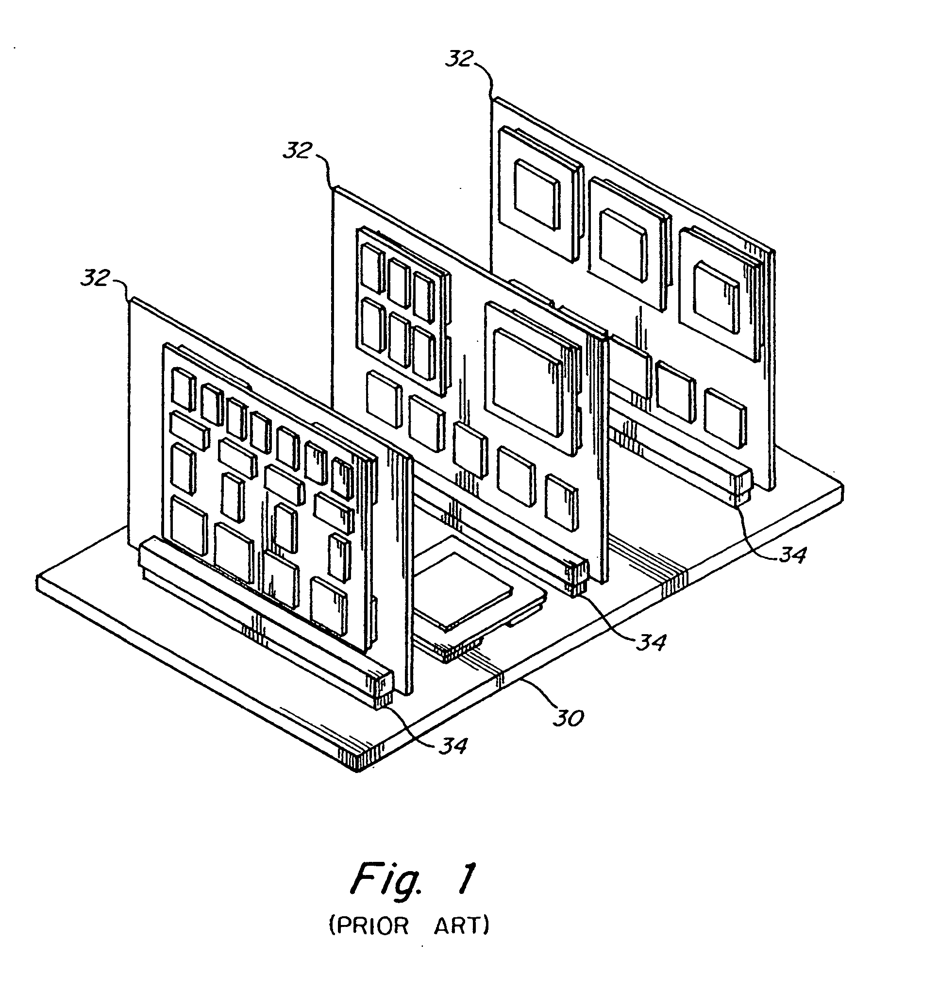
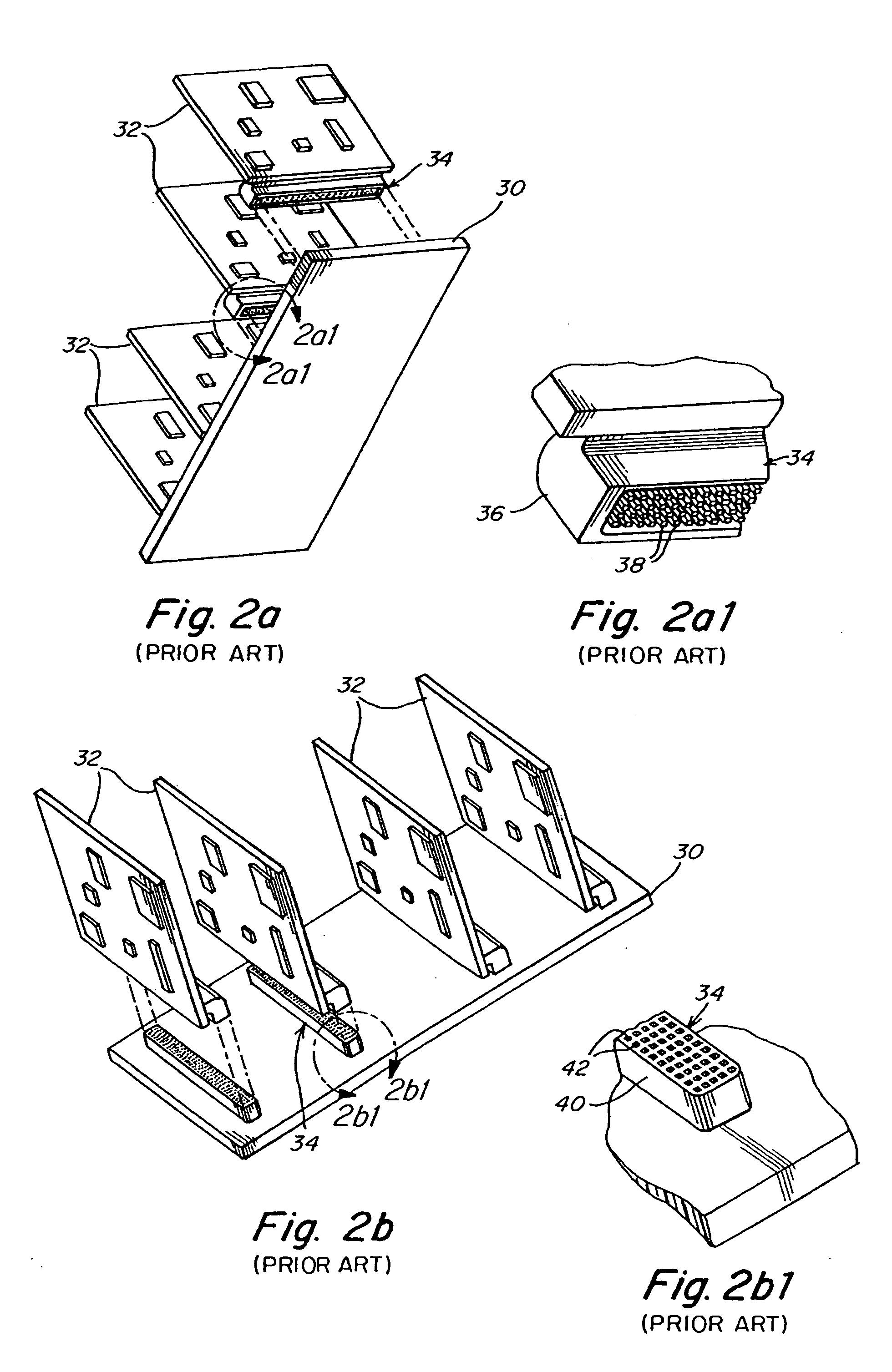
CROSS-REFERENCE TO RELATED APPLICATIONS [0001] This patent application claims priority to U.S. Provisional Patent Application No. 60 / 486,363 filed Jul. 11, 2003.FIELD OF THE INVENTION [0002] The present invention is directed to electrical switches, and in particular to multi-contact woven electrical switches. BACKGROUND [0003] Components of electrical systems sometimes need to be interconnected using electrical connectors and / or switches to provide an overall, functioning system. These components may vary in size and complexity, depending on the type of system. For example, referring to FIG. 1, a system may include a backplane assembly comprising a backplane or motherboard 30 and a plurality of daughter boards 32 that may be interconnected using a connector 34, which may include an array of many individual pin connections for different traces etc., on the boards. For example, in telecommunications applications where the connector connects a daughter board to a backplane, each connec...

Claims


Application Information

Patent Timeline
Patent Type & Authority Applications(United States)
IPC IPC(8): H01H1/06H01H1/38
CPCH01H1/06H01H2203/01H01H2001/0005H01H1/38H01H1/02H01H1/14
Inventor SWEETLAND, MATTHEWMORAN, JAMESSUH, NAM P.
Owner METHODE ELETRONICS INC
Learn More