Vortex inducing rotor for screening apparatus for papermaking pulp

a technology of vortex inducing rotor and papermaking pulp, which is applied in the direction of screening, sedimentation settling tank, screening, etc., can solve the problems of fiber flocs, debris, fiber flocs, and fibers that are easy to plug with fibers, and require significant energy. , the effect of pulse generation

Inactive Publication Date: 2005-03-03
GL & V MANAGEMENT HUNGARY KFT
View PDF22 Cites 5 Cited by
  • Summary
  • Abstract
  • Description
  • Claims
  • Application Information

AI Technical Summary

Benefits of technology

[0011] One of the objects of this invention is to create a rotor that can keep a screen working properly wit

Problems solved by technology

As actually practiced in the Industry, screens with apertures sufficiently small to remove the undesirable particles are prone to plugging with fiber, fiber flocs, and debris.
But such pulse generation can have several negative effects.
For example, significant energy is required in order to produce the pulses, and the rotor

Method used


Image

  • Vortex inducing rotor for screening apparatus for papermaking pulp
  • Vortex inducing rotor for screening apparatus for papermaking pulp
  • Vortex inducing rotor for screening apparatus for papermaking pulp

Examples


Embodiment Construction

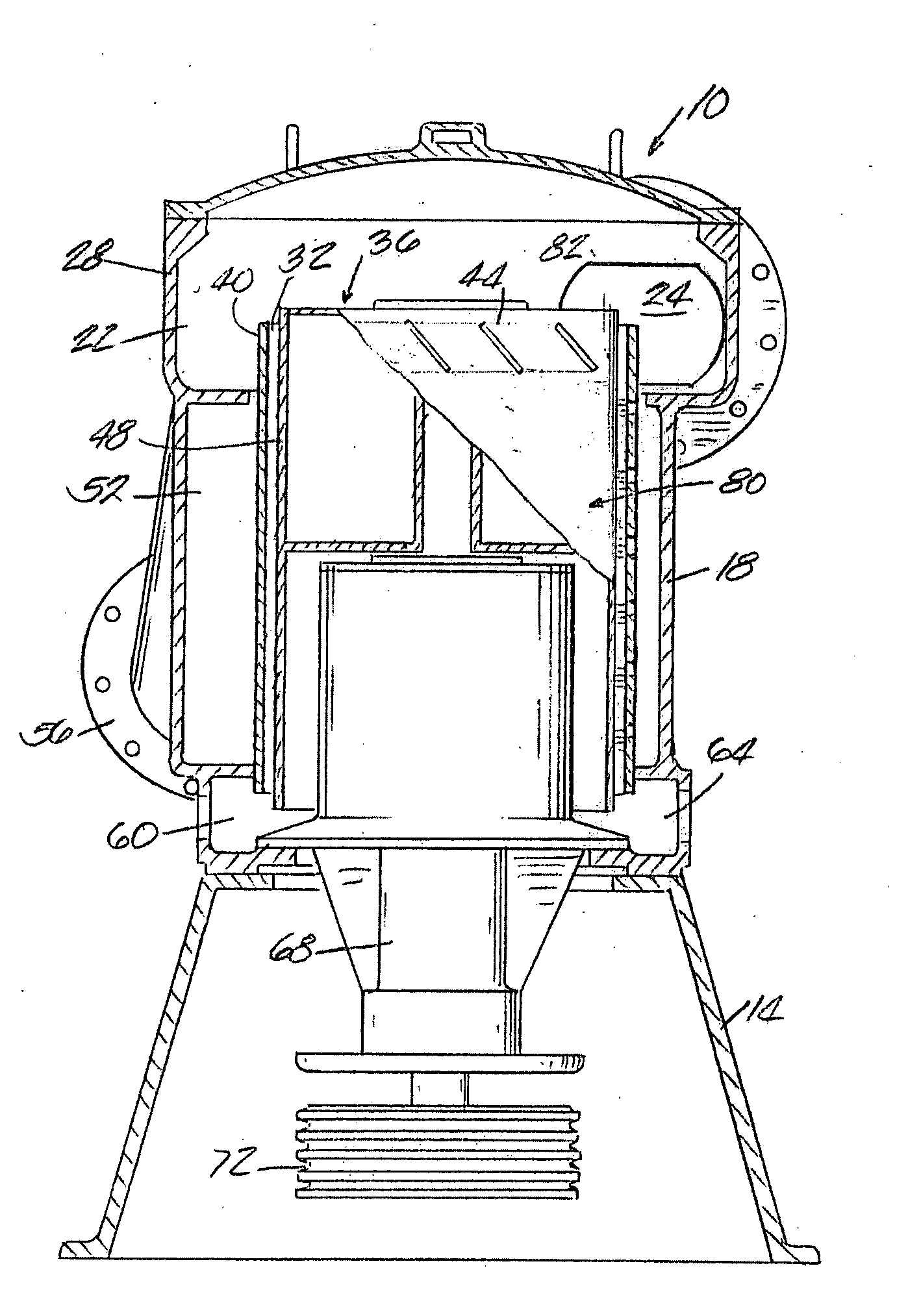
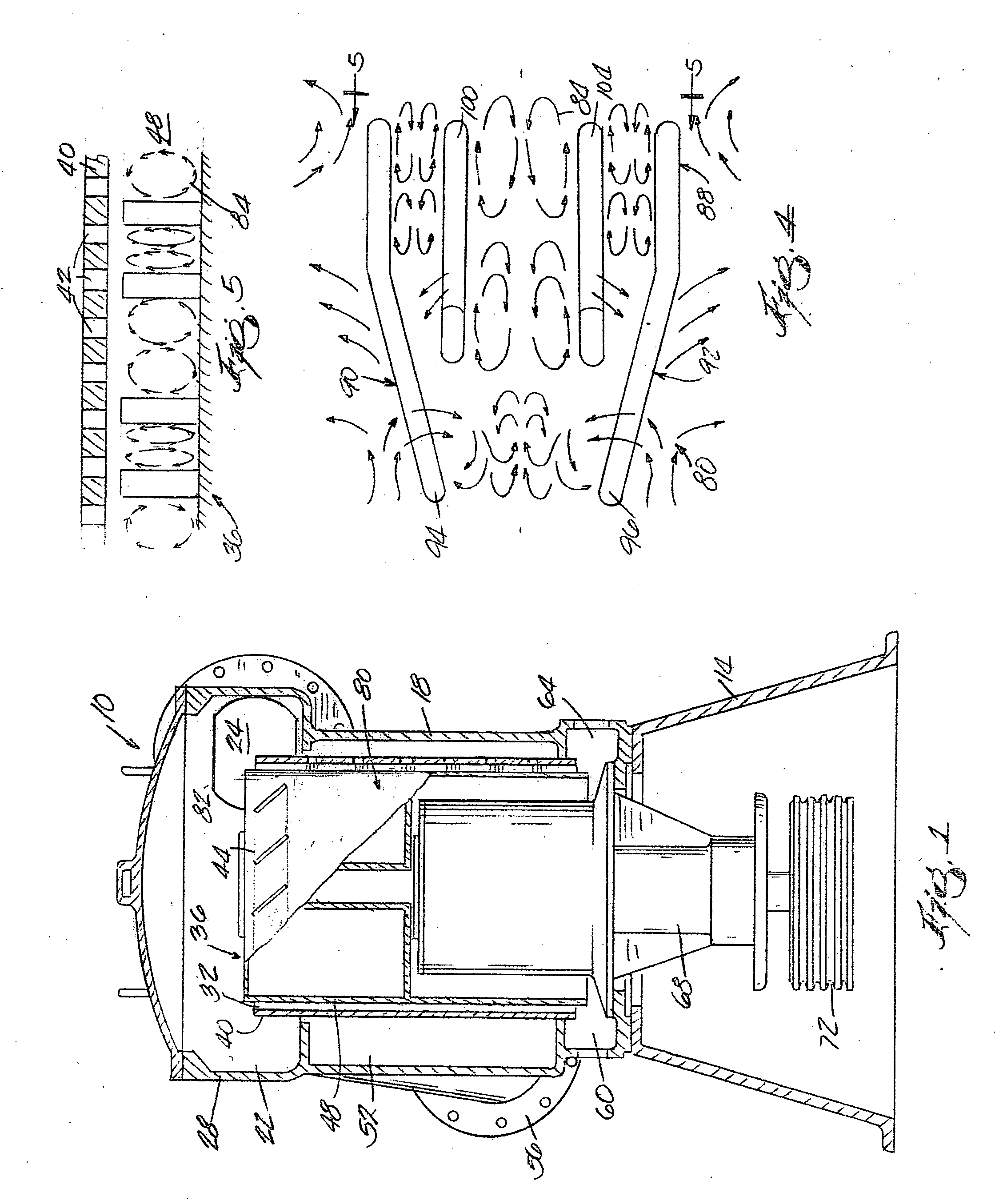
[0025] Referring to FIG. 1, common features of a hydrodynamic device such as pulp screening equipment can be seen. A screening apparatus 10 is made up of a base 14 upon which a housing 18 is mounted. (The apparatus shown here is vertically oriented, but it is known that a screening apparatus may be in any orientation between horizontal and vertical.) Housing 18 has an end mounted inlet chamber 22 with a pulp inlet 24 through which pulp is tangentially fed for screening. The pulp flows around and over inlet wall 28 into pulp entrance 32 which is defined by the annular space that forms a screening chamber between the portion of rotor 36 projecting above the perforated portion of a screen 40.

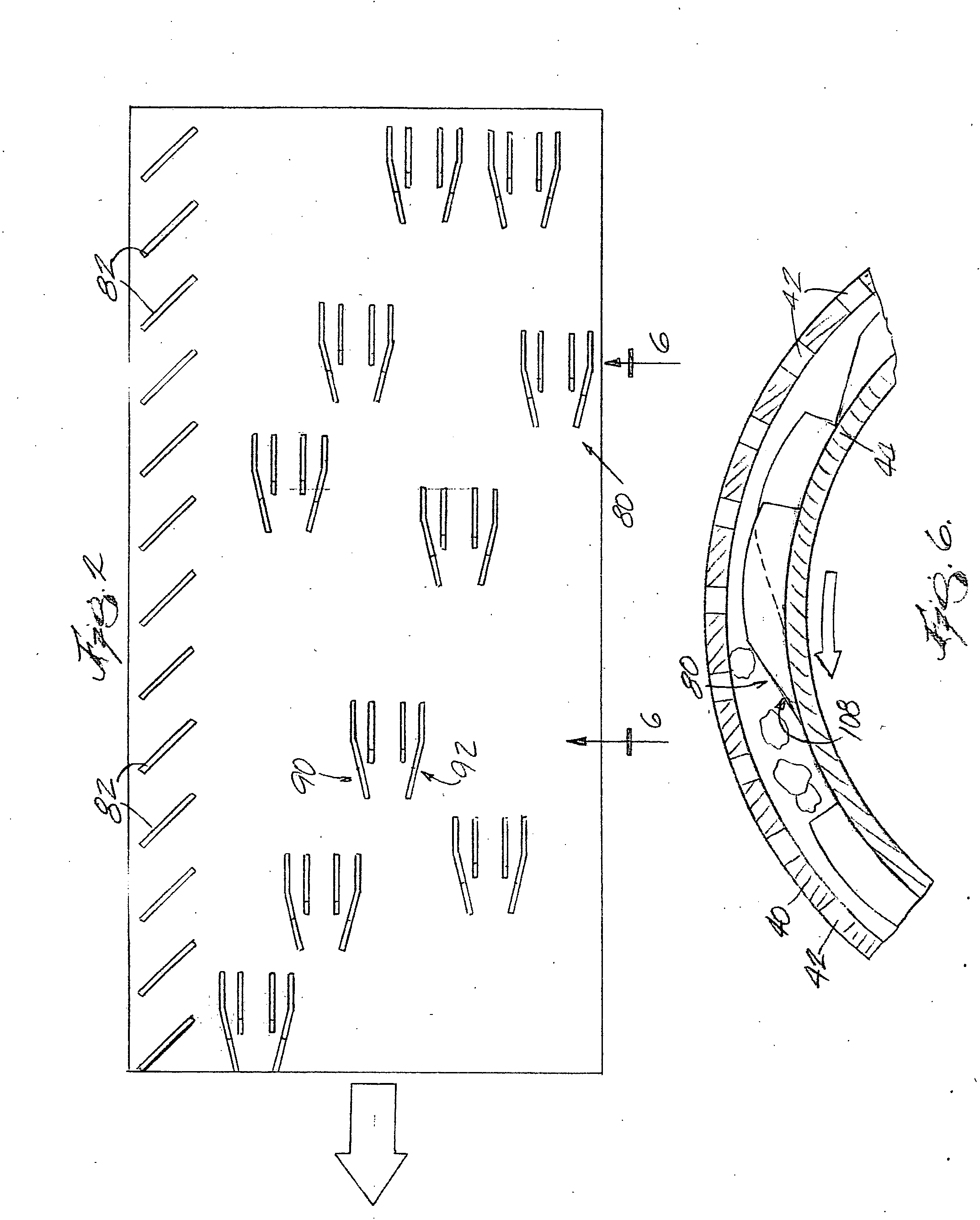
[0026] Rotor 36 has a closed top and a generally cylindrical surface 44, and the screen 40 has apertures 42 through which accepted fiber along with pulp liquor has a normal outflow. More particularly, the screen 40 is a cylindrical screen having a circumferentially continuous apertured zone. The a...


PUM

PropertyMeasurementUnit
Pressureaaaaaaaaaa
Angleaaaaaaaaaa
Radiusaaaaaaaaaa

Abstract

A rotor having a longitudinal axis of rotation and including an outer surface adjacent a screen surface. The rotor also includes a plurality of sets of radially extending, relative to the rotor axis, adjacent vane members attached to the rotor surface, each set including at least four adjacent vane members with equally spaced apart and parallel trailing edges ending in a common plane. The two outermost vane members have leading edges forward of the two most inside vane members, with the leading edges forward of the two most inside vane members being angled toward its next adjacent vane. The height of the two innermost vane members is about half of the height of the two outermost vane members. Each of the outermost vane members is angled relative to the circumferential direction of travel of the rotor by each of the outermost having vane members with a leading edge that is angled relative to its trailing edge. Each of the vane members has a leading edge forming an acute angle relative to the surface of the rotor and has a top edge with the same radius of curvature as the screen. The plurality of sets of vane members are spaced out throughout a screening chamber defined between the rotor surface and the screen in the direction of the rotor axis. The rotor outer surface does not have any longitudinally extending lifting bodies that produce pressure pulses throughout the screening chamber.

Description

BACKGROUND OF THE INVENTION [0001] This invention relates generally to machinery for screening paper-making pulp and, more particularly, to a screening apparatus having an enhanced rotor for promoting screening efficiency together with power conservation. [0002] The Pulp and Paper Industry uses pressure screens to separate undesirable materials from usable fiber in the Industries various processes. The ideal embodiment of a pressure screen would remove all undesirable materials without the loss of desired fibers, without requiring any additional dilution of the fiber suspension, and with the minimum possible power consumption. As actually practiced in the Industry, screens with apertures sufficiently small to remove the undesirable particles are prone to plugging with fiber, fiber flocs, and debris. Plugging of the screen apertures eliminates the passage of all fiber. To allow the screen to operate, the screen must be cleared of potentially blocking materials. [0003] Numerous variat...

Claims


Application Information

Patent Timeline
IPC IPC(8): B07B1/20D21D5/02
CPCD21D5/026B07B1/20
Inventor MEESE, RICHARD G.GALLAGHER, BRIAN J.CROSSLEY, BRUCE R.BURNS, JAMES P. JR.
Owner GL & V MANAGEMENT HUNGARY KFT
Why Eureka
Try Eureka