Orbital weld head

a weld head and orbital technology, applied in the direction of soldering apparatus, manufacturing tools, auxillary welding devices, etc., can solve the problems of reducing the accuracy of welds, and reducing the number of workpieces with known weld heads. achieve the effect of more accurate and consistent welds

Active Publication Date: 2005-03-03
SWAGELOK CO
View PDF16 Cites 7 Cited by
  • Summary
  • Abstract
  • Description
  • Claims
  • Application Information

AI Technical Summary

Benefits of technology

[0007] The present invention provides a rotor and insert configuration that produces a consistent arc gap and no binding without the need for the additional clearance. Thus, the present weld head design allows for the inevitable expansion

Problems solved by technology

The arc welding process produces a substantial amount of heat.
This can degrade any plastic components of the weld head and thereby limit the number of workpieces the k

Method used


Image

  • Orbital weld head
  • Orbital weld head
  • Orbital weld head

Examples


first embodiment

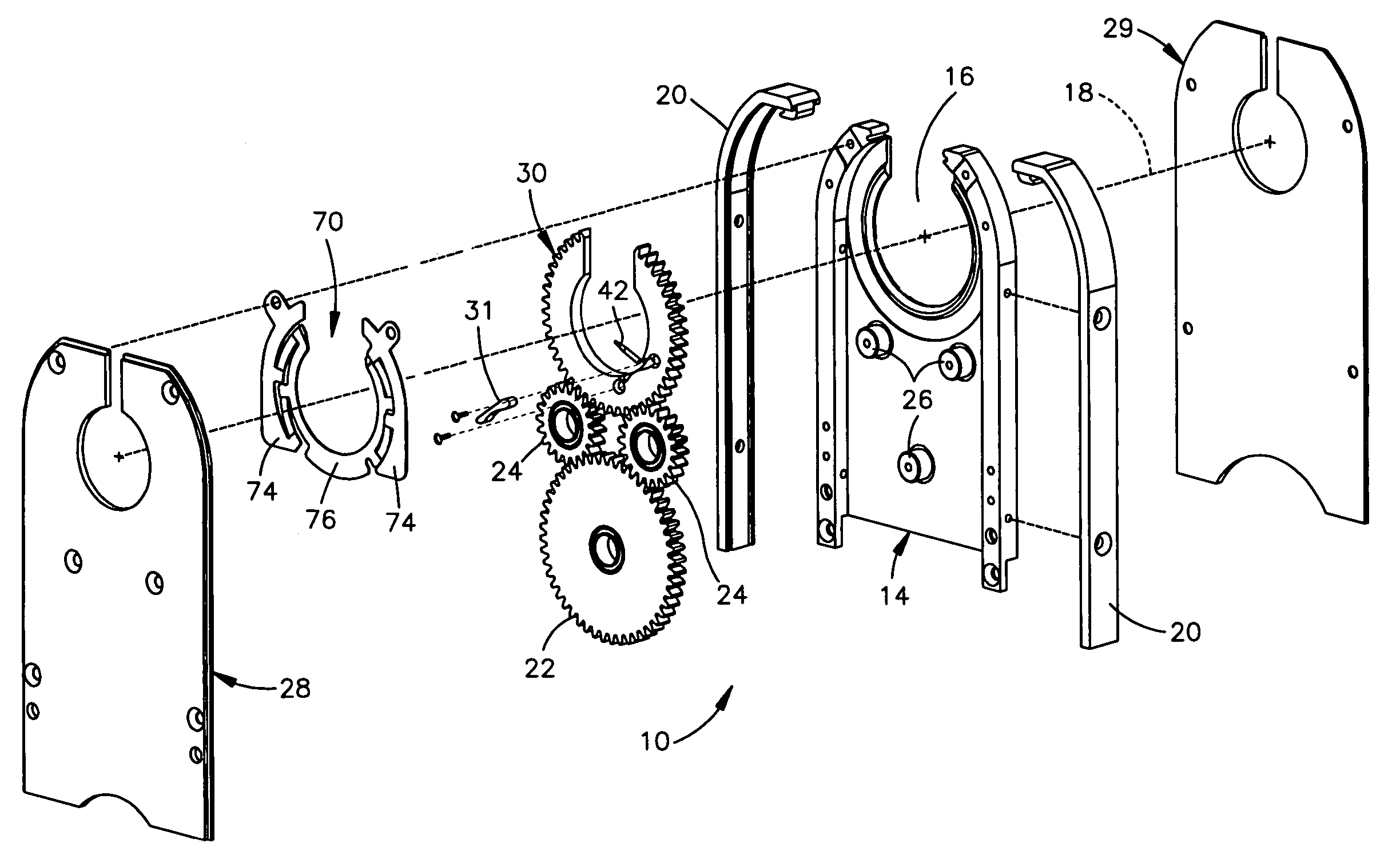
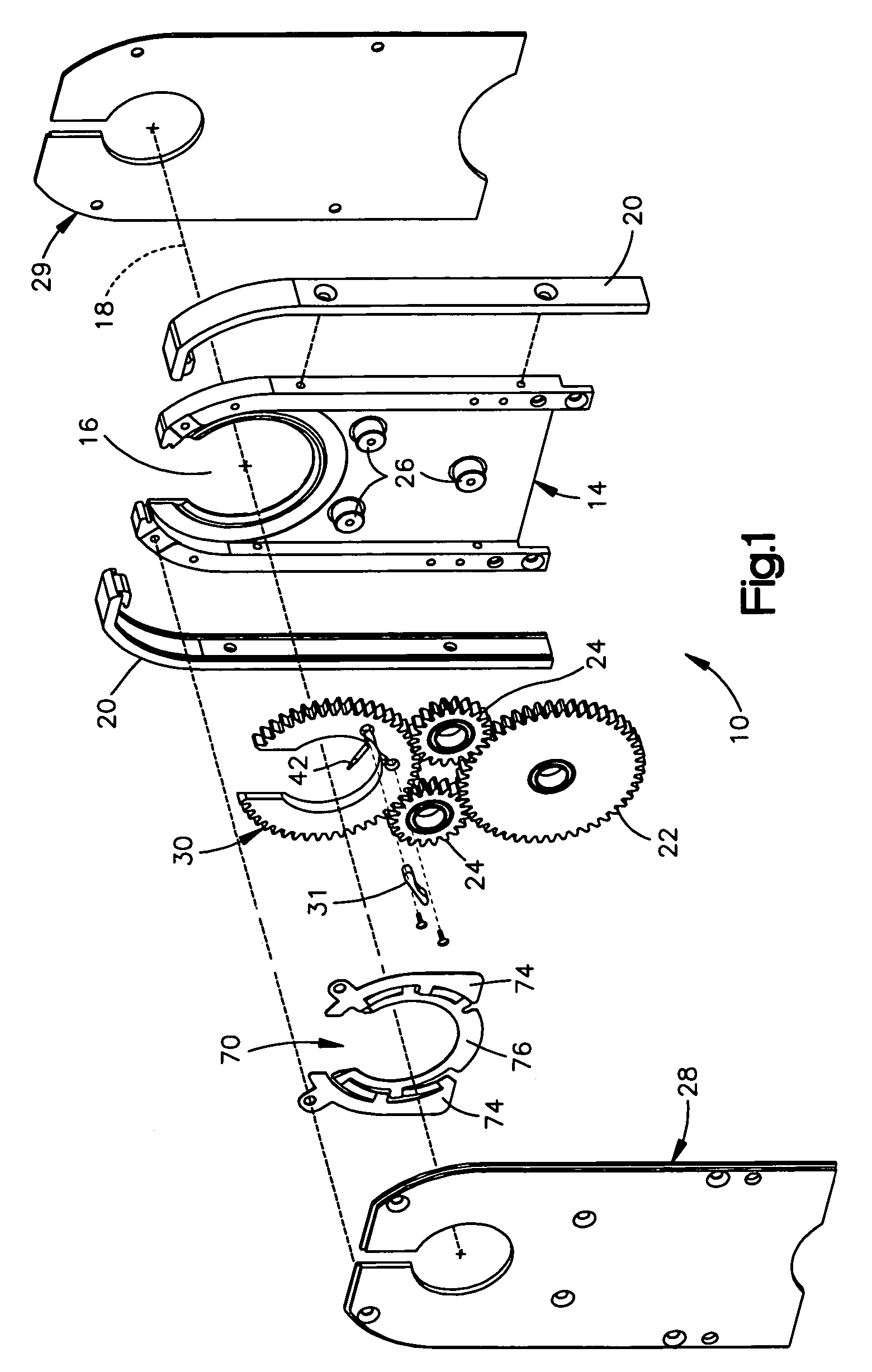
[0027] The present invention relates to an orbital weld head and is applicable to weld heads of varying and different constructions. As representative of the invention, FIG. 1 illustrates a portion of an orbital weld head 10 in accordance with the invention.

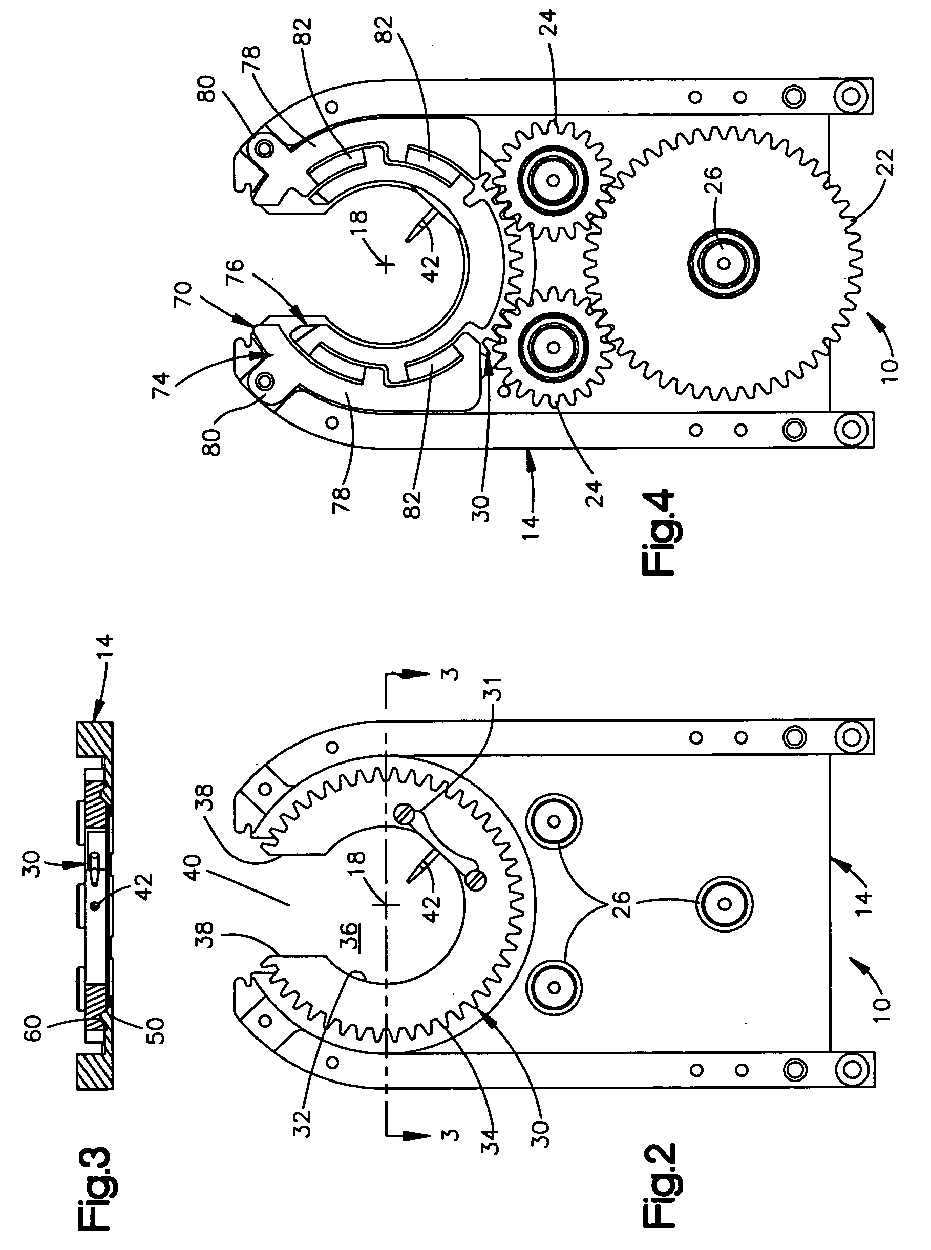
[0028] The weld head 10 includes an insert 14 that serves as the base of the weld head, supporting many of the other parts of the weld head. The insert 14 has a generally circular work opening 16 centered on an axis of rotation 18 (FIG. 2) of the weld head 10. Two electrically insulating edge pieces 20 are secured to the insert 14, in a manner not shown.

[0029] The insert 14 may be made from plastic but is preferably made from an electrically conductive metal, such as stainless steel, copper, or bronze. Metal typically can absorb more heat than plastic without deforming, and metal is more stable when it does absorb heat. As a result, the insert 14 if made from metal can absorb a relatively large amount of heat. This can help enab...

second embodiment

[0075]FIG. 7 illustrates a portion of a weld head 10a in accordance with the invention. In the weld head 10a, the positions of the boss and the track are reversed. Specifically, the insert 14a has a trapezoidal groove or track 60a, while the rotor 30a has a trapezoidal boss 50a that is received in the track. The engagement of the boss 50a of the rotor 30a in the track 60a of the insert 14a positions the rotor relative to the insert. This engagement also maintains electrical contact between the rotor 30a and the insert 14a, even when the parts are heated and expand unevenly, as described above.

[0076]FIGS. 10 and 11 illustrate an alternative one-piece brush / spring or brush 90. The brush 90 is formed as one piece from an electrically conductive material, such as metal. The brush has an overall C-shaped configuration when viewed in plan as in FIG. 10.

[0077] The brush has an inner portion, or brush portion 92, and an outer portion, or spring portion 94. The inner portion 92 of the brush...


PUM

PropertyMeasurementUnit
Temperatureaaaaaaaaaa
Angleaaaaaaaaaa

Abstract

An orbital weld head includes a metal insert and rotor. The covers are made from mica laminate. A metal spring/brush that is preferably one piece side loads the rotor against the insert. The rotor and insert have interengaging portions, preferably trapezoidal, that cause the rotor to move axially when it expands from heat, thus minimizing binding.

Description

RELATED APPLICATION [0001] This application claims the benefit of the filing date of U.S. Provisional Application No. 60 / 481,216 filed Aug. 12, 2003, the entire disclosure of which is incorporated by reference.BACKGROUND OF THE INVENTION [0002] Orbital welding involves the use of a weld head that retains an electrode that revolves (orbits) around a workpiece as it welds the workpiece. The workpiece may be, for example, two cylindrical tubes having abutting end portions to be welded together end to end. [0003] A known orbital welder includes a weld head that has two jaws defining an opening between the jaws. The weld head is placed in a welding position relative to the workpiece by moving the workpiece through the opening between the jaws. The workpiece is then in a circular work space inside a rotor. The rotor carries an electrode. When the weld head is actuated, the rotor rotates about the workpiece, and the electrode orbits about the workpiece. An electric arc is produced between ...

Claims


Application Information

Patent Timeline
IPC IPC(8): B23K9/028
CPCB23K2201/06B23K9/0286B23K2101/06B23K9/028
Inventor OYSTER, PETERAMES, NATHANMIZER, CRAIGHORVATH, TOM
Owner SWAGELOK CO
Why Eureka
Try Eureka