Slurry iron removal device

A slurry and permanent magnet technology, applied in magnetic separation, solid separation, chemical instruments and methods, etc., can solve the problems that impurity iron cannot be completely removed, fine iron removal cannot be achieved, and iron removal efficiency is low, so as to achieve iron removal Good effect, complete and uniform iron removal

Inactive Publication Date: 2021-04-20
HUBEI XITIAN TECH CO LTD
View PDF0 Cites 0 Cited by
  • Summary
  • Abstract
  • Description
  • Claims
  • Application Information

AI Technical Summary

Problems solved by technology

[0003] The traditional slurry iron removal method is to insert multiple magnet rods into the static slurry for adsorption. This method not only has low iron removal efficiency, but also the magnetic rods that absorb more iron will affect the further adsorption of iron. , resulting in poor iron removal effect, impurity iron in the slurry cannot be completely removed
[0004] At present, some iron removal equipments have appeared. Although they can handle large quantities of slurries, the existing iron removal equipment usually enters the magnetic cavity with large quantities of slurries together, and the flow rate is fast, so there are still insufficient iron removal effects. Good, uneven iron removal, high impurity iron residues in the slurry, etc., can not meet the requirements of fine iron removal

Method used


Image

  • Slurry iron removal device

Examples


Embodiment Construction

[0022] Exemplary embodiments of the present invention will be described in more detail below with reference to the accompanying drawings. Although exemplary embodiments of the present invention are shown in the drawings, it should be understood that the invention may be embodied in various forms and should not be limited to the embodiments set forth herein. Rather, these embodiments are provided for more thorough understanding of the present disclosure and to fully convey the scope of the present disclosure to those skilled in the art.

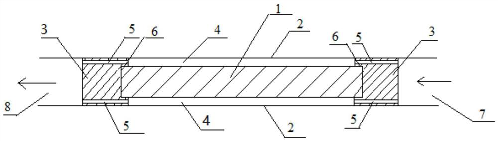
[0023] Please refer to figure 1 , figure 1 It is a longitudinal sectional view of a specific embodiment of the slurry iron removal device provided by the present invention.

[0024] like figure 1 As shown, the slurry iron removal device of the present invention includes a permanent magnet 1 and a casing 2, wherein the casing 2 is a cavity with openings at both ends surrounded by side walls and a hollow interior; the permanent magnet 1 is lo...


PUM

PropertyMeasurementUnit
Thicknessaaaaaaaaaa

Abstract

The invention discloses a slurry iron removal device. The device comprises a permanent magnet and a shell, the permanent magnet is arranged in the shell, two connectors are arranged at the two ends of the permanent magnet respectively, the permanent magnet is fixed between the two connectors, the connectors are fixedly connected with the inner wall of the shell, a gap between the permanent magnet and the shell and the connector form a slurry flowing cavity, and at least one through hole is formed in the connector, so that slurry enters the slurry flowing cavity from the connector at one end, flows through the surface of the permanent magnet and flows out from the connector at the other end. The slurry flowing cavity with the thickness of only several mm is formed between the permanent magnet and the shell, all slurry can completely pass through the surface of the permanent magnet for iron removal, the good iron removal effect is guaranteed through the uniform flow speed and the uniform and consistent magnetic field, and the iron removal device is particularly suitable for fine iron removal occasions.

Description

technical field [0001] The invention relates to a slurry iron removal device, which belongs to the technical field of fine iron removal. Background technique [0002] Ceramics, chemical industry, smelting and other industries all need to remove iron from the slurry to meet the quality requirements of the product. As the requirements of material science become higher and higher, the requirements for residual impurity iron in products are also higher and higher, so fine iron removal is required. [0003] The traditional slurry iron removal method is to insert multiple magnet rods into the static slurry for adsorption. This method not only has low iron removal efficiency, but also the magnetic rods that absorb more iron will affect the further adsorption of iron. , resulting in poor iron removal effect, impurity iron in the slurry cannot be completely removed. [0004] At present, there are some iron removal equipments. Although they can handle a large amount of slurry, the e...

Claims


Application Information

Patent Timeline
IPC IPC(8): B03C1/02
Inventor 邢长生张艳兵李辉闫伟周伟刘志坚李新
Owner HUBEI XITIAN TECH CO LTD
Why Eureka
Try Eureka