Vibration type actuator drive controller and method of controlling drive speed of vibration type actuator

a technology of drive controller and vibration type, which is applied in the direction of dynamo-electric converter control, piezoelectric/electrostrictive device details, instruments, etc., can solve the problems of difficult acceleration operation usually under the same progress, operation differences may be generated, and vibration type motors may be stopped in some cases, so as to achieve smooth acceleration operation

Inactive Publication Date: 2005-03-03
CANON KK
View PDF8 Cites 18 Cited by
  • Summary
  • Abstract
  • Description
  • Claims
  • Application Information

AI Technical Summary

Benefits of technology

The present invention has been made in the light of the above-mentioned problems, and it is, therefore, an object of the present invention to provide a vibration type actuator drive controller which is capable of smoothly carrying out an acceleration operation and...

Problems solved by technology

Further, a drive frequency may undergo the feedback control in a state where the drive frequency is made lower than a resonance frequency of a vibration member due to a start delay resulting from a mechanical time constant of a system having the vibration type motor and a load to which the vibration type motor is connected, and as a result, the vibration type motor may be stopped in some cases.
Also, since the stored gradient information strictly changes if there is a fluctuation in environmental conditions such as a temperature, it is difficult to carry out an acceleration operation usually under the same progress.
In particular, in an apparatus which is configured so that a vibration type motor and another actuator operate in conjunction with each other, there is a possibility tha...

Method used


Image

  • Vibration type actuator drive controller and method of controlling drive speed of vibration type actuator
  • Vibration type actuator drive controller and method of controlling drive speed of vibration type actuator
  • Vibration type actuator drive controller and method of controlling drive speed of vibration type actuator

Examples


first embodiment

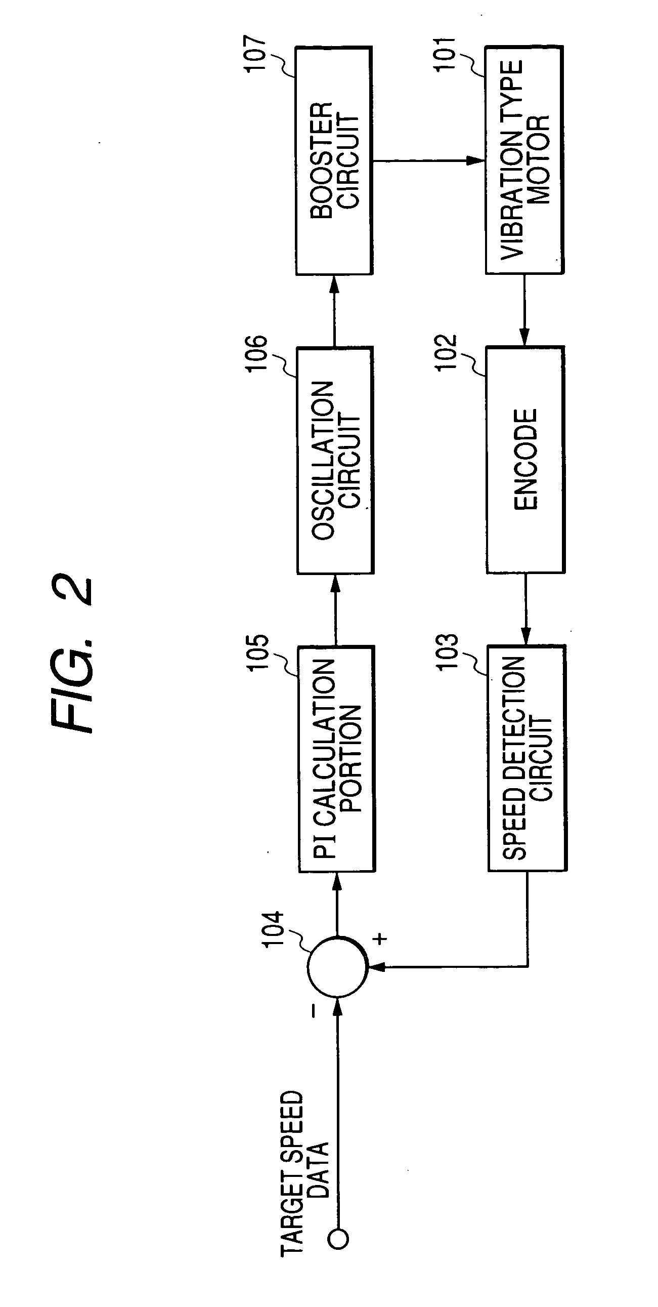
FIG. 2 is a block diagram showing a configuration of a circuit for controlling a vibration type motor as a vibration type actuator drive controller according to a first embodiment of the present invention.

Referring to FIG. 2, reference numeral 101 designates a vibration type motor. While not illustrated in FIG. 2, the vibration type motor 101 includes an electromechanical energy transducer, a vibration member, a movable member and the like. Then, the vibration type motor 101 is a motor having a configuration in which A.C. voltages of two phases are applied to the electromechanical energy transducer to generate a progressive vibration wave in the vibration member, and resultant vibration energy is transmitted to the movable member brought into pressure contact with the vibration member.

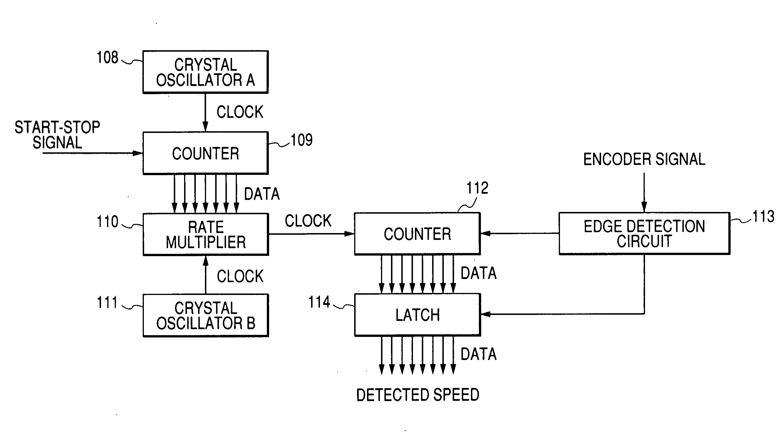
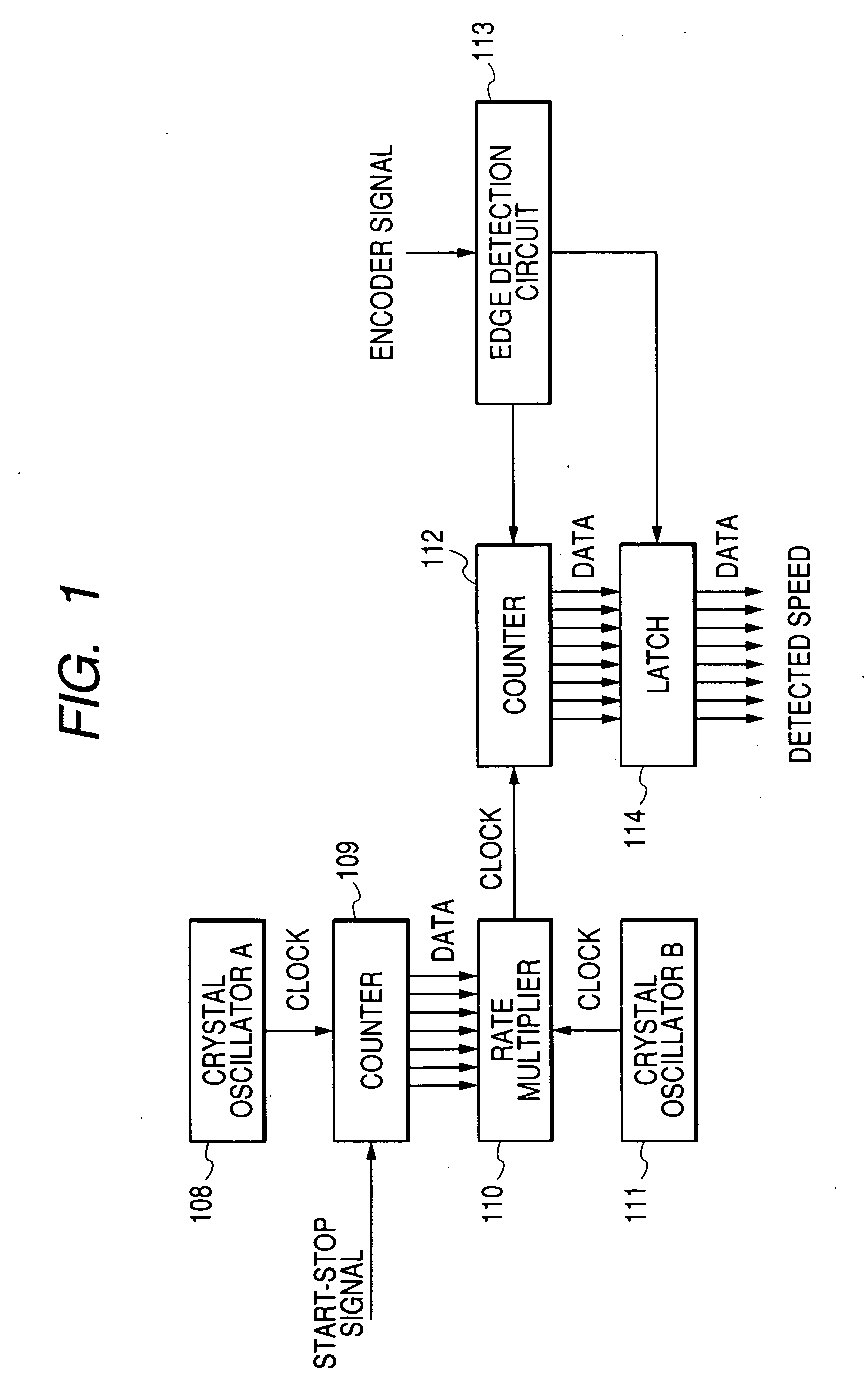
A rotary encoder 102 is mounted to an output shaft of the vibration type motor 101. A pulse signal having a frequency which is proportional to a drive speed of the vibration type motor 101 is outpu...

second embodiment

FIG. 3 is a block diagram showing a configuration of a speed detection circuit according to a second embodiment of the present invention. Note that since a configuration of the circuit for controlling the vibration type motor according to the second embodiment is basically the same as that of the circuit for controlling the vibration type motor according to the first embodiment shown in FIG. 2, its description is omitted here for the sake of simplicity, and only the speed detection circuit as a constituent element different from that of the first embodiment is described below.

In the circuit for controlling the vibration type motor in the second embodiment, a clock signal is supplied from a crystal oscillator C 115 to all the constituent elements of this control circuit, and hence all the constituent elements operate synchronously with this clock signal.

Referring now to FIG. 3, reference numeral 116 designates a down counter. A value of an acceleration command issued from the out...

third embodiment

In a third embodiment, a description will be given to a color image forming apparatus in which the circuit for controlling a vibration type motor of the present invention is installed.

FIG. 4 is a front view showing a construction of the color image forming apparatus according to the third embodiment of the present invention.

Referring to FIG. 4, reference numeral 1 designates a reader portion for reading information of an original. Reference symbols 2a, 2b, 2c and 2d designate image forming portions which are constituted by LED arrays 3a, 3b, 3c and 3d, photosensitive drums 4a, 4b, 4c and 4d, and the like, respectively. An image read by the reader portion 1 is developed in the photosensitive drums 4a, 4b, 4c and 4d. A yellow color, a magenta color, a cyan color, and a black color of the image captured by the reader 1 are developed in the image forming portions 2a, 2b, 2c and 2d, respectively. These four colors are composited to allow the full color copy to be carried out. Referen...


PUM


Abstract

This disclosure relates to a technique for smoothly carrying out an acceleration operation and a deceleration operation for a vibration type actuator to prevent a situation where in starting the vibration type actuator, a drive frequency is reduced to become lower than a resonance frequency to stop the vibration type actuator. A first counter performs up-count from a first value to a second value larger than the first value at predetermined time intervals in accelerating the vibration type actuator. A rate multiplier outputs a clock signal having a frequency corresponding to the count value. A second counter measures a period of a pulse signal, the period being adapted to change in correspondence to a drive speed of the vibration type actuator, by counting the clock pulses. The drive speed of the vibration type actuator is controlled such that the measured pulse period becomes a predetermined target value.

Description

BACKGROUND OF THE INVENTION 1. Field of the Invention The present invention relates in general to a vibration type actuator drive controller, and more particularly to a vibration type actuator drive controller and a method of controlling a drive speed of a vibration type actuator adapted to excite a vibration member by applying an A.C. signal to an electromechanical energy transducer to obtain a driving force. 2. Related Background Art In a vibration type actuator adapted to excite a vibration member by applying an A.C. signal to an electromechanical energy transducer to obtain a driving force, heretofore, various proposals have been made for an acceleration / deceleration method for a vibration type motor which is one of vibration type actuators. For example, Japanese Patent Application Laid-Open No. H06-269182 discloses a technique in which to stably accelerate and decelerate a vibration type motor, characteristics of the vibration type motor, especially, gradients of a drive s...

Claims


Application Information

Patent Timeline
IPC IPC(8): H01L41/04H02N2/12H02N2/00H02N2/14H02P25/02
CPCH02P25/027H02N2/142H02P25/032
Inventor YAMAMOTO, SHINJI
Owner CANON KK
Why Eureka
Try Eureka