Imaging apparatus and flicker reduction method

a technology of image processing and flicker reduction, which is applied in the field of image processing apparatus, can solve the problems of insufficient suppression of flicker, and deterioration of image quality, and achieve the effect of improving image quality

Active Publication Date: 2005-03-03
SONY CORP
View PDF9 Cites 83 Cited by
  • Summary
  • Abstract
  • Description
  • Claims
  • Application Information

AI Technical Summary

Benefits of technology

[0056] Accordingly, the present invention aims to reduce fluorescent-lamp flicker components regardless of the combination of the power-supply frequency and the vertical synchronization frequency of the imaging apparatus without detecting the frequency of the power supply for driving the fluorescent lamp and also aims to realize a high-speed shutter required for electronic camera-shake correction.
[0058] In another aspect, the present invention provides a method for reducing fluorescent-lamp flicker components contained in a video signal obtained by photographing a subject by an XY address scanning-type imaging device under the illumination of a fluorescent lamp, the method including, when the set vertical synchronization frequency of the imaging apparatus including the imaging device is denoted as fv (Hz) and N is a positive integer: a shutter control step of setting a shutter speed to an electronic shutter speed at which the exposure time becomes N / 120 seconds in a case where 120 / fv is an integer, and of setting the shutter speed to an electronic shutter speed at which the exposure time becomes N / 100 seconds in a case where 100 / fv is an integer; and a flicker reduction process step of reducing flicker components by estimating flicker components from the video signal and by correcting the video signal in accordance with the estimated result in a state in which the electronic shutter speed is set in the shutter control step.
[0064] Moreover, for this reason, it is not necessary to detect the power-supply frequency fp, and the shutter control means of the imaging apparatus need only make a determination as to the set vertical synchronization frequency fv (video system) of the imaging apparatus. Furthermore, when electronic camera-shake correction is to be performed, a high-speed shutter with an exposure time shorter than the vertical period 1 / fv (seconds) can be realized by setting, for example, N=1, and an improvement in image quality can be achieved by the high-speed shutter.

Problems solved by technology

As a result, in the above-described method, flicker cannot be suppressed sufficiently.
However, in practice, the above-described color change is added, and the image quality is deteriorated considerably.
Consequently, the deterioration of the image quality becomes more pronounced.
Then, when flicker, which is not continuous in the time axis, that completes in one field (one picture plane), occurs in case 3 or case 4 of FIG. 7, in which the shutter is set to a high-speed shutter, since a distinction between picture pattern components by the subject and fluorescent-lamp flicker components in the video signal from the imaging device cannot be made from the very beginning, it is not possible to reduce flicker components by the flicker reduction method using the above-described continuity of flicker.
As a result, it is not possible to reduce flicker components by the flicker reduction method using the above-described continuity of flicker.
However, when flicker that is not continuous in the time axis and that completes in one vertical period (one picture plane) occurs in the manner described above, since a distinction between picture pattern components and fluorescent lamp flicker components in the video signal from the imaging device cannot be made from the very beginning, it is not possible to detect the power-supply frequency.
However, in this method, the size and the cost of the imaging apparatus system increase.
Furthermore, when the shutter is set to a normal shutter rather than being set to a high-speed shutter, there are problems in electronic camera-shake correction, as described below.
However, in such electronic camera-shake correction, camera shake between picture planes (between fields or between frames) can be corrected, but commonly called afterimage blur due to camera shake which occurs during an exposure period cannot be corrected from the viewpoint of principles.
That is, although camera shake between picture planes can be reduced by camera-shake correction, since the afterimage blur remains as is, the image quality deteriorates by the unbalance thereof.

Method used


Image

  • Imaging apparatus and flicker reduction method
  • Imaging apparatus and flicker reduction method
  • Imaging apparatus and flicker reduction method

Examples


Embodiment Construction

[0087] [Embodiment of Imaging Apparatus: FIGS. 8 and 9]

[0088] (System Configuration: FIG. 8)

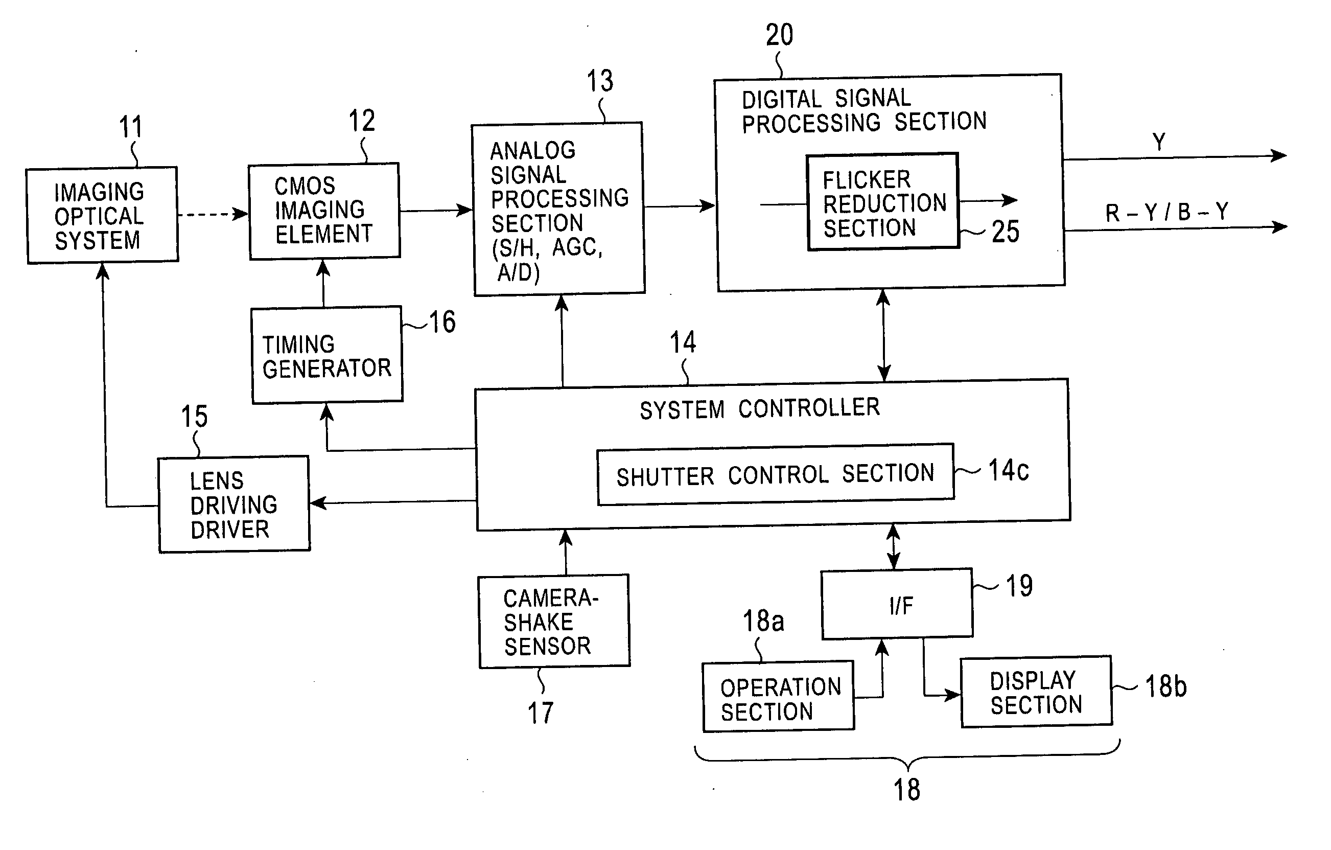
[0089]FIG. 8 shows the system configuration of an embodiment of an imaging apparatus of the present invention, and also shows a video camera, which is selectively set to either the NTSC system (fv=60 Hz) or the PAL system (fv=50 Hz) and in which a CMOS imaging device is used as an XY address scanning-type imaging device.

[0090] In the imaging apparatus of this embodiment, that is, the video camera, light from a subject enters a CMOS imaging device 12 via an imaging optical system 11. The light is photoelectrically converted at the CMOS imaging device 12, and an analog video signal is obtained from the CMOS imaging device 12.

[0091] The CMOS imaging device 12 is formed in such a manner that a plurality of pixels having a photodiode (photogate), a transfer gate (shutter transistor)., a switching transistor (address transistor), an amplifier transistor, a resetting transistor (reset gate), etc....


PUM


Abstract

In an XY address scanning-type imaging apparatus, such as a CMOS imaging apparatus, a high-speed shutter which is capable of reducing fluorescent-lamp flicker components and which is required for electronic camera-shake correction can be realized. When the vertical synchronization frequency is denoted as fv (Hz) and N is a positive integer, the shutter is set to N / 120 seconds when 120 / fv is an integer, and the shutter is set to N / 100 seconds when 100 / fv is an integer. In the NTSC system, when camera-shake correction is ON, the shutter speed is set to {fraction (1 / 120)} seconds, and when camera-shake correction is OFF, the shutter speed is set to {fraction (1 / 60)} seconds. In the PAL system, when camera-shake correction is ON, the shutter speed is set to {fraction (1 / 100)} seconds, and when camera-shake correction is OFF, the shutter speed is set to {fraction (1 / 50)} seconds. The same applies to the progressive system.

Description

BACKGROUND OF THE INVENTION [0001] 1. Field of the Invention [0002] The present invention relates to an imaging apparatus, such as a video camera or a digital still camera, in which an XY address scanning-type imaging device (imager, image sensor) such as a CMOS (Complementary Metal Oxide Semiconductor) imaging device is used, and to a method for reducing fluorescent lamp flicker which occurs in a video signal obtained from the imaging device when a subject is photographed by the imaging apparatus under the illumination of a fluorescent lamp. [0003] 2. Description of the Related Art [0004] When a subject is photographed by a video camera under the illumination of a fluorescent lamp which is powered on by a commercial AC power-supply, an intensity change with respect to time, that is, so-called fluorescent lamp flicker, occurs in the video signal of the photographed output due to the difference between the frequency (twice the commercial AC power-supply frequency) of the luminance ch...

Claims


Application Information

Patent Timeline
Patent Type & Authority Applications(United States)
IPC IPC(8): H04N5/235H04N5/335H04N5/351H04N5/353H04N5/357H04N5/374H04N5/378
CPCH04N5/2357H04N5/235H04N23/70H04N23/745H04N23/76H04N25/57
Inventor KINOSHITA, MASAYA
Owner SONY CORP
Why Eureka
Try Eureka