Radar apparatus

a technology of radar and apparatus, applied in the field of radar equipment, can solve the problems of inaccurate reception time tp and large , achieve the effects of improving the accuracy of object detection, reducing and increasing the intensity of laser ligh

Inactive Publication Date: 2005-03-03
DENSO CORP
View PDF4 Cites 74 Cited by
  • Summary
  • Abstract
  • Description
  • Claims
  • Application Information

AI Technical Summary

Benefits of technology

[0014] In view of the foregoing problems, it is an object of the present invention to provide a radar apparatus which can enhance an accuracy of detection of an object.
[0017] Thus, the radar apparatus can change the intensity of the laser light outputted from the optical means according to a situation by using the intensity changing means. For example, the intensity changing means increases the intensity of the laser light when an object at a long distance or an object with low reflectance to the laser light is detected. To the contrary, the intensity changing means decreases the intensity of the laser light when an object at a short distance or an object with high reflectance to the laser light is detected. As a result, it can be prevented that a detection signal corresponding to an intensity of the reflected light becomes too large. Therefore, an accuracy of detection of the object can be improved.

Problems solved by technology

In this case, the correction amount Δα becomes too large and the reception time tp cannot be calculated accurately.

Method used


Image

  • Radar apparatus
  • Radar apparatus
  • Radar apparatus

Examples


first embodiment

[0028] A radar apparatus according to the first embodiment of the present invention is mounted in an inter-vehicle distance control system. The inter-vehicle distance control system controls a distance to a preceding vehicle at a desired distance and alarms when an obstacle exists in a predetermined area.

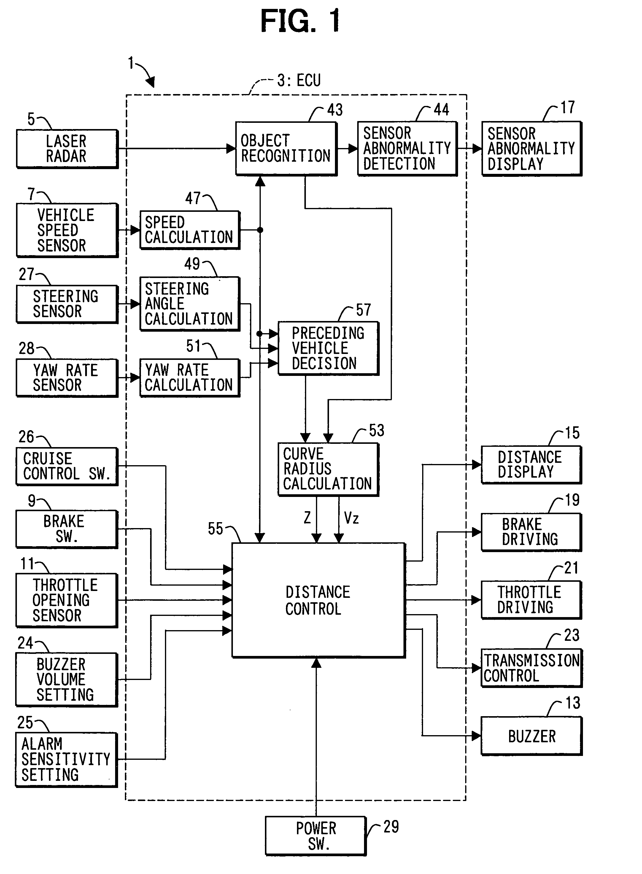
[0029] As shown in FIG. 1, an inter-vehicle distance control system 1 includes an electronic control unit (ECU) 3 as a main part. The ECU 3 includes a microcomputer, an input / output interface and the like.

[0030] The ECU 3 receives detection signals from a laser radar sensor 5, a vehicle speed sensor 7, a brake switch 9 and a throttle opening sensor 11. The ECU 3 outputs driving signals to an alarm buzzer 13, a distance display 15, a sensor abnormality display 17, a brake driving device 19, a throttle driving device 21 and an automatic transmission controller 23. The ECU 3 connects to a buzzer volume setting device 24 for setting volume of the alarm buzzer 13, an alarm sensitivity ...

second embodiment

[0083] In the first embodiment, the intensity of the laser lights is switched according to the speed of the vehicle. To the contrary, in the second embodiment, the intensity of the laser lights is switched according to a distance to a reflecting object.

[0084] In the second embodiment, the processing to recognize the object is attained as shown in FIG. 8. The laser lights are emitted at step S110. When step S110 is performed in the first repetition of the processing, the intensity of the laser lights is set to a default value. For example, the default value is set to be high to detect all of the reflecting objects in the measurement area 91. When step S110 is performed in the second repetition of the processing or later, the intensity of the laser lights is set to the intensity set at step S160 or S170 in the previous repetition.

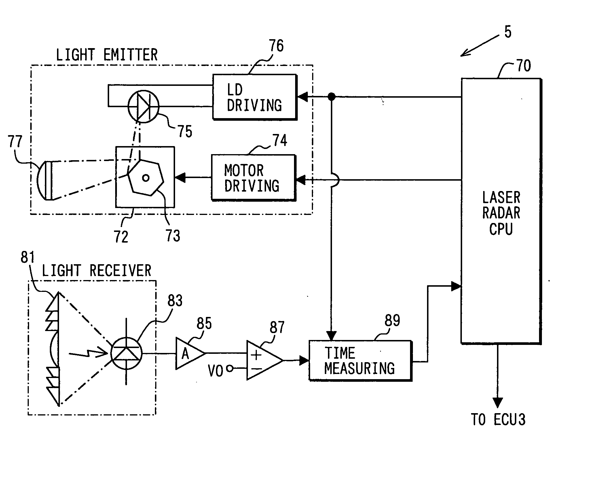
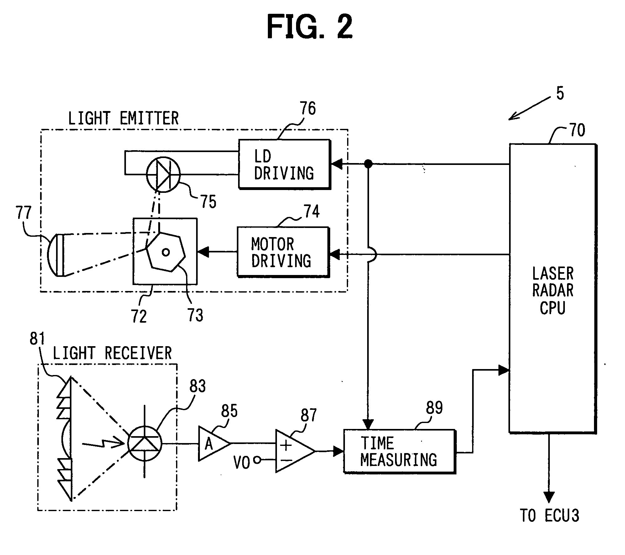
[0085] When the reflected light is received, the laser radar CPU 70 of the laser radar sensor 5 reads the time point data every scanning line at step S120....

third embodiment

[0090] In the third embodiment, the intensity of the laser lights is switched according to the reflected light intensity data At of the scanning data.

[0091] In the third embodiment, the processing to recognize the object is attained as shown in FIG. 9. The laser lights are emitted at step S210. When step S210 is performed in the first repetition of the processing, the intensity of the laser lights is set to the default value. For example, the default value is set to be high similarly to the second embodiment. When step S210 is performed in the second repetition of the processing or later, the intensity of the laser lights is set to the intensity set at step S250 or S260 in the previous repetition.

[0092] When the reflected light is received, the laser radar CPU 70 of the laser radar sensor 5 reads the time point data every scanning line at step S220. At step S230, the distance data and the reflected light intensity data Δt are calculated from the read time point data. These calcula...


PUM


Abstract

In a radar apparatus, a laser light generating device generates a laser light. An optical device reflects the laser light to output it in a predetermined direction. The optical device has at least two reflective surfaces with different reflectance to the laser light. A reflected light detecting device detects a reflected light when the laser light is reflected by an object. An object detecting device detects the object based on the reflected light. An intensity changing device changes an intensity of the outputted laser light by switching the reflective surfaces. Thus, it can be prevented that an intensity of the reflected light becomes too large and an accuracy of detection of the object can be improved.

Description

CROSS REFERENCE TO RELATED APPLICATION [0001] This application is based on Japanese Patent Application No. 2003-311776 filed on Sep. 3, 2003, the disclosure of which is incorporated herein by reference. FIELD OF THE INVENTION [0002] The present invention relates to a radar apparatus which emits a laser light and receives a reflected light to detect an object. BACKGROUND OF THE INVENTION [0003] A radar apparatus is disclosed in U.S. Pat. No. 5,805,527 (corresponding to JP-A-H9-236661). This radar apparatus emits a laser light and receives a reflected light from an object. This radar apparatus measures a distance to the object based on a time period between an emission time when the laser light is emitted and a reception time when the reflected light is received. Therefore, it is necessary that the radar apparatus detects the reception time accurately. [0004] In order to detect the reception time, the radar apparatus converts the reflected light to a received signal whose magnitude co...

Claims


Application Information

Patent Timeline
Patent Type & Authority Applications(United States)
IPC IPC(8): G01S17/931G01C3/08G01S7/481G01S17/42
CPCG01S7/4811G01S7/4817G01S17/936G01S17/42G01S7/4868G01S17/931
Inventor ANDO, TAKAMASATERUI, TAKEKAZUINOMATA, MAKOTO
Owner DENSO CORP
Why Eureka
Try Eureka