Fiber optic sensing instrument and system with fiber of adjustable optical path length and method of using it

a fiber optic and optical path technology, applied in the field of fiber optic sensing instruments, can solve the problems of ambiguity rendering the detection ambiguous or even meaningless, the simplest form cannot detect the location of pressure or temperature in the extended area, and the use of fairly complicated mathematics

Inactive Publication Date: 2005-03-03
MORISON W DON +4
View PDF2 Cites 12 Cited by
  • Summary
  • Abstract
  • Description
  • Claims
  • Application Information

AI Technical Summary

Benefits of technology

To achieve the above and other objects, the present invention is directed to a fiber optic sensing system incorporating a fiber having an adjustable optical path length. A sensing optical fiber is applied to a structure to be monitored to detect displacement or the like by changing its optical path length. A reference optical fiber has a fixed optical path length. An adjustable length optical fiber is controllably adjusted in its optical path length. The three optical fibers form optical paths whose light outputs are caused to interfere. The adjustable length optical fiber is adjusted until an interference fringe appears. The quantity to be detected is derived from the maximum of the interference fringe. Several sensing optical fibers can be multiplexed; by staggering their optical path lengths, their interference fringes can be separated sufficiently to resolve them.

Problems solved by technology

For example, if a long fiber is used to sense pressure or temperature over an extended area, the simplest form cannot detect the location of the pressure or temperature in the extended area.
Second, the range of phase differences must fall within 2π; otherwise, the resulting phase ambiguity renders the detection ambiguous or even meaningless.
However, fairly complicated mathematics are used to calculate strain and temperature from the group delay and dispersion as determined from the interferogram.
However, the SOFO system introduces an undesirable complexity in that two fibers must be present in the structure to be monitored.
Also, the analyzer of the SOFO system cannot demultiplex and analyze signals from multiple sensors without the use of an optical switch to select the signal from one of the sensors.,

Method used


Image

  • Fiber optic sensing instrument and system with fiber of adjustable optical path length and method of using it
  • Fiber optic sensing instrument and system with fiber of adjustable optical path length and method of using it
  • Fiber optic sensing instrument and system with fiber of adjustable optical path length and method of using it

Examples


Embodiment Construction

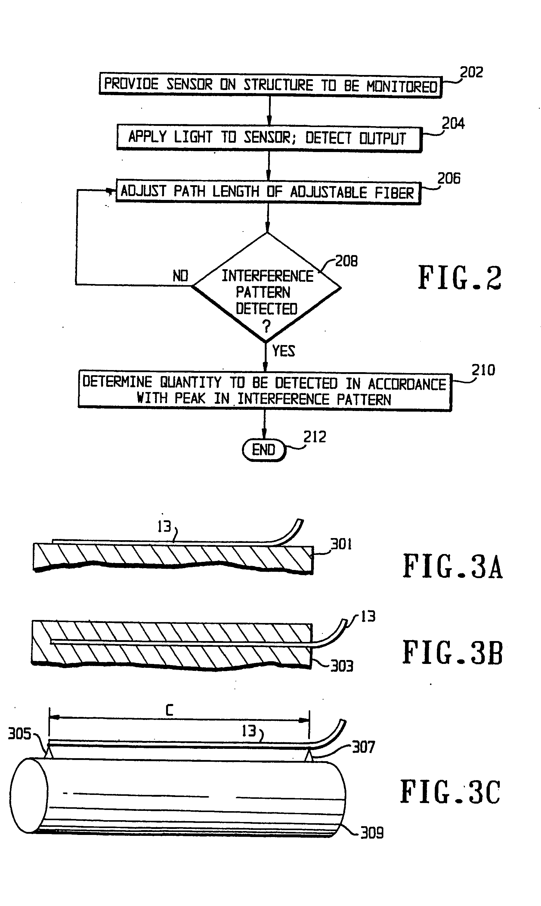
A preferred embodiment of the present invention and variations thereon will be described in detail with reference to the drawings, in which like reference numerals refer to like elements throughout.

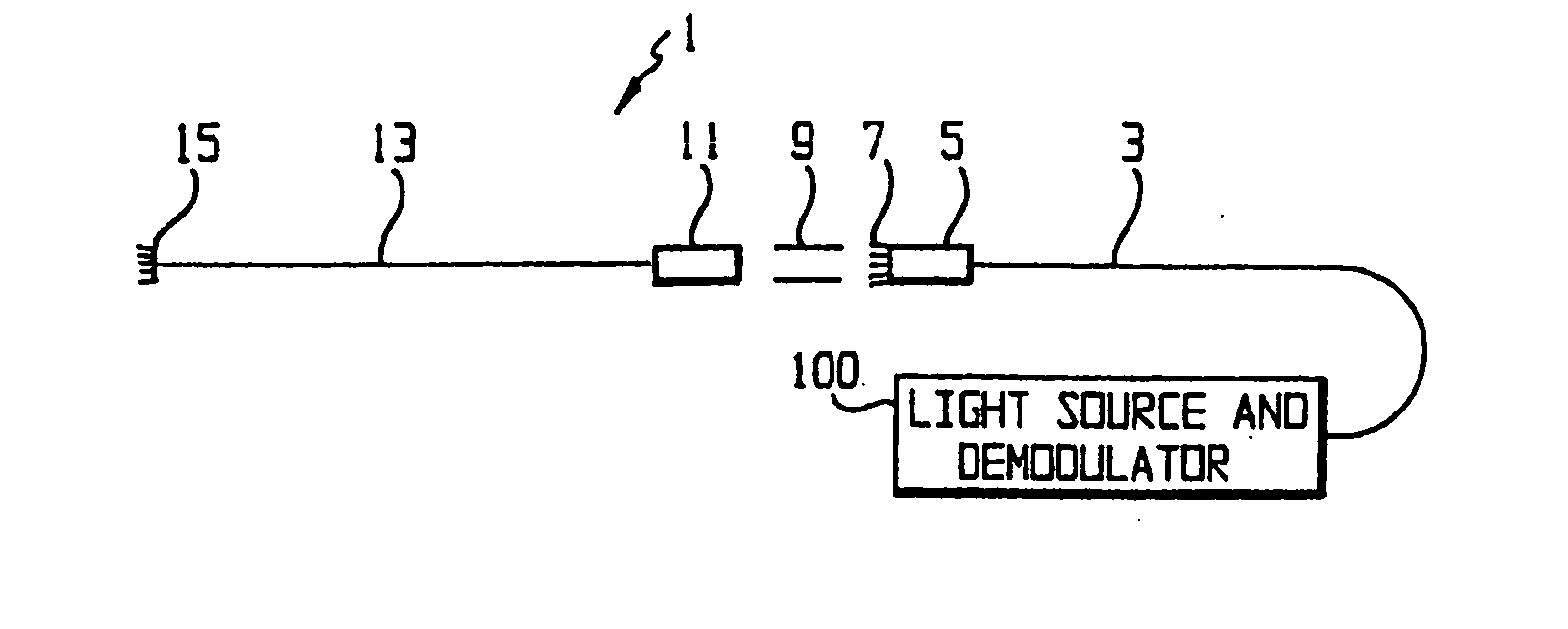
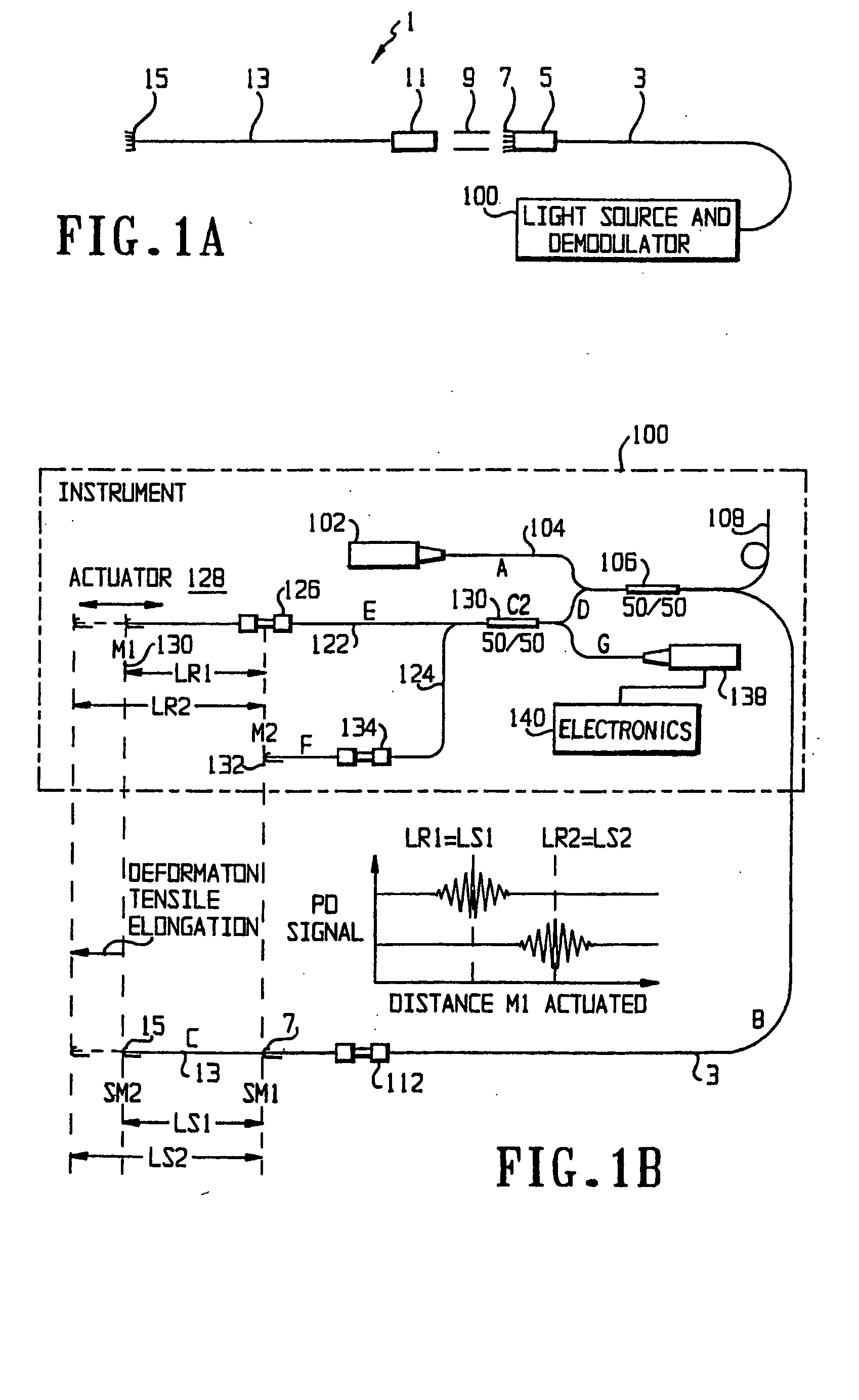
FIG. 1A shows a schematic diagram of a sensor for use with the instrument according to the preferred embodiment. The sensor 1 includes a lead fiber 3, preferably a single-mode optical fiber, terminated by a lead ceramic ferrule 5 and a lead mirror 7 formed as a partially mirrored surface on the end of the lead fiber 3. A ceramic sleeve 9 is used to attach the ferrule 5 to another ceramic ferrule 11, which is in turn attached to a sensor fiber 13, which is also preferably a single-mode optical fiber. The sensor fiber 13 ends in a sensor mirror 15, which, like the lead mirror 7, is formed as a partially mirrored surface on the end of the sensor fiber 13. The sensor 1 is connected to an instrument 100 which functions as both a light source and a demodulator.

The sensor 1 is installed such t...


PUM


Abstract

An interoferometric fiber optic sensing system uses three optical fibers. A sensing optical fiber is applied to a structure to be monitored to detect displacement or the like by changing its optical path length. A reference optical fiber has a fixed optical path length. An adjustable length optical fiber is controllably adjusted in its optical path length. The three optical fibers form optical paths whose light outputs are caused to interfere. The adjustable length optical fiber is adjusted until an interference fringe appears. The quantity to be detected is derived from the maximum of the interference fringe. Several sensing optical fibers can be multiplexed; by staggering their optical path lengths, their interference fringes can be separated sufficiently to resolve them.

Description

FIELD OF THE INVENTION The present invention is directed to a fiber optic sensing instrument for sensing deflections, displacements, or other physical conditions and more particularly to such a sensing instrument having a fiber of adjustable optical path length, and is further directed to a system and method using such a sensing instrument. The adjustable length can be used for spatial division multiplexing, extending the range of displacements detectable by the sensing instrument, or other purposes. DESCRIPTION OF RELATED ART The use of optical fibers to sense deflections, displacements, temperatures and other physical conditions is well known. Typically, such sensors operate by interferometry. An interferometric fiber optic sensing instrument, in its simplest form, operates by splitting light from a light source between two fibers. The first fiber, a sensing fiber, is exposed to the physical condition to be sensed, while the second fiber, a reference fiber, is not. The light pas...

Claims


Application Information

Patent Timeline
Patent Type & Authority Applications(United States)
IPC IPC(8): G01D5/353
CPCG01D5/35303
Inventor MORISON, W. DONMANUELPILLAI, GERALDTENNYSON, RODERICK C.CHERPILLOD, THIERRYROUSE, DOMINIC
Owner MORISON W DON
Why Eureka
Try Eureka