Optical pulse demultiplexer

a multi-channel, optical pulse technology, applied in multiplex communication, wavelength-division multiplex systems, instruments, etc., can solve the problems of difficult optimal adjustment of polarization and phase, inability to convert such ultra-high-speed optical pulse signals in intact state into electrical signals, etc., to suppress the other remaining channel components and reduce polarization-dependency. , the effect of small polarization dependen

Inactive Publication Date: 2005-03-03
NAT INST OF INFORMATION & COMM TECH
View PDF2 Cites 17 Cited by
  • Summary
  • Abstract
  • Description
  • Claims
  • Application Information

AI Technical Summary

Benefits of technology

[0008] According to this embodiment of the invention, by using saturable absorption optical elements, desired channel components are separated from an input signal light in the time domain with a little polarization-dependency. Furthermore, it is possible to suppress the other remaining channel components by providing a non-linear waveform shaper.

Problems solved by technology

It is not possible to convert such ultra high-speed optical pulse signals in the intact state into electrical signals at a reception terminal.
Accordingly, it is very difficult to optimally adjust the polarization and phase.

Method used


Image

  • Optical pulse demultiplexer
  • Optical pulse demultiplexer
  • Optical pulse demultiplexer

Examples


Embodiment Construction

[0014] Exemplary embodiments of the invention are explained below in detail with reference to the drawings.

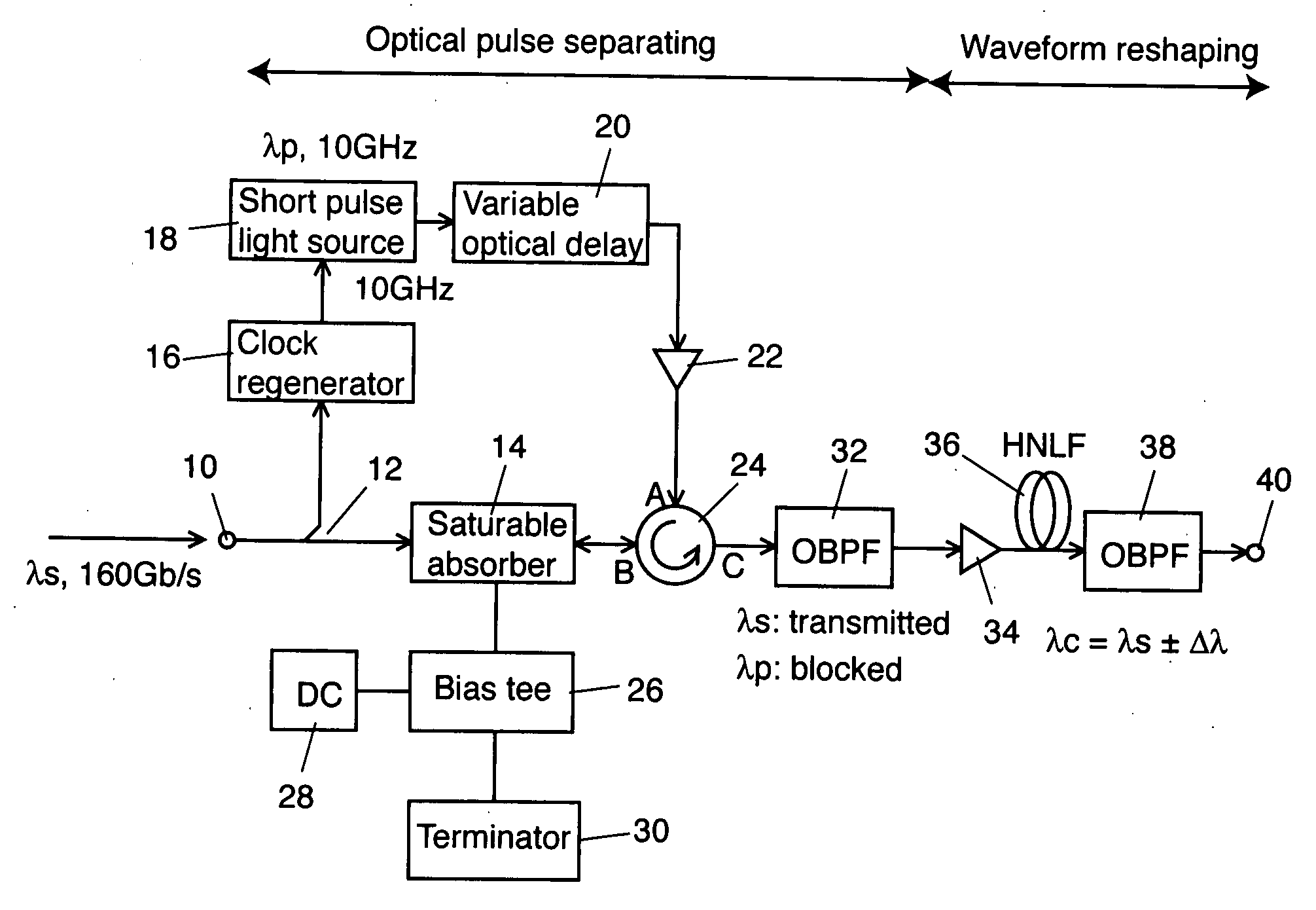
[0015]FIG. 1 shows a schematic block diagram of an exemplary embodiment according to the invention. In this embodiment, when an optical pulse signal of 160 Gb / s (16 data lights at a base rate of 10 Gb / s are time-division-multiplexed) enters an input terminal 10 from an optical transmission line, optical pulse signals of 10 Gb / s are demultiplexed from the input optical signal light.

[0016] An optical splitter 12 splits the optical pulse signal light of 160 Gb / s with a wavelength λs having entered the input terminal 10 into two portions. The optical splitter 12 applies one portion of the split lights to a saturable absorption optical element 14 having a cross-absorbing modulation effect and the other portion to a clock regenerator 16.

[0017] The saturable absorption optical element 14 is an element having such characteristics that the element 14 absorbs the signal wavelengths wh...


PUM

PropertyMeasurementUnit
frequencyaaaaaaaaaa
frequencyaaaaaaaaaa
center frequencyaaaaaaaaaa

Abstract

In an optical pulse demultiplexer according to the invention, an optical splitter splits an input pulse signal light having a signal wavelength into a firs portion and a second portion. An optical clock generator generates an optical clock having a clock wavelength at a predetermined frequency corresponding to 1/n (n is integer not less than 2) of a bit rate of the input pulse signal light out of the first portion of the output lights from the optical splitter. The clock wavelength is different from the signal wavelength. A saturable absorption optical element, to which the optical clock generated by the optical clock generator and the second portion enter, separates a channel component corresponding to the predetermined frequency out of the second according to the optical clock. An optical filter extracts an optical component of the signal wavelength out of the light output from the saturable absorption optical element. A nonlinear waveform shaper suppresses a low level part of the light output from the first optical filter.

Description

CROSS REFERENCE TO RELATED APPLICATIONS [0001] This application claims priority to Japanese Patent Application No. 2003-303994, filed Aug. 28, 2003, the entire contents of which are incorporated herein by reference. FIELD OF THE INVENTION [0002] This invention generally relates to an optical pulse demultiplexer, and more specifically relates to an optical pulse demultiplexer to demultiplex an optical pulse of desired timing from a high-speed optical pulse train. BACKGROUND OF THE INVENTION [0003] An ultra high-speed optical pulse signal is generated by time-division-multiplexing a plurality of optical pulse signals (tributary channels) for carrying data at the same reference bit rate (base rate). For instance, when the base rate is 10 Gb / s and the number of multiplexing signals is 16, an ultra high-speed pulse signal of 160 Gb / s is generated. In such case that an ultra high-speed optical pulse signal of a single wavelength is to be generated, a plurality of low-speed optical pulse s...

Claims


Application Information

Patent Timeline
Patent Type & Authority Applications(United States)
IPC IPC(8): G02F2/00G02F1/015H04J14/02H04J14/08H04L7/00
CPCH04B10/299H04L7/0075H04J14/08
Inventor MIYAZAKI, TETSUYA
Owner NAT INST OF INFORMATION & COMM TECH
Why Eureka
Try Eureka