Optical multiplexer/demultiplexer, optical integrated circuit and light transceiver using the same
a technology of optical integrated circuits and light transceivers, applied in the direction of optical elements, semiconductor lasers, instruments, etc., can solve the problems of communication interference, increase the light leakage from the core, and the inability to achieve high isolation and a smaller waveguide size, and achieve small polarization dependence, high isolation characteristic, and reduced size
- Summary
- Abstract
- Description
- Claims
- Application Information
AI Technical Summary
Benefits of technology
Problems solved by technology
Method used
Image
Examples
first embodiment
[0050] First Embodiment
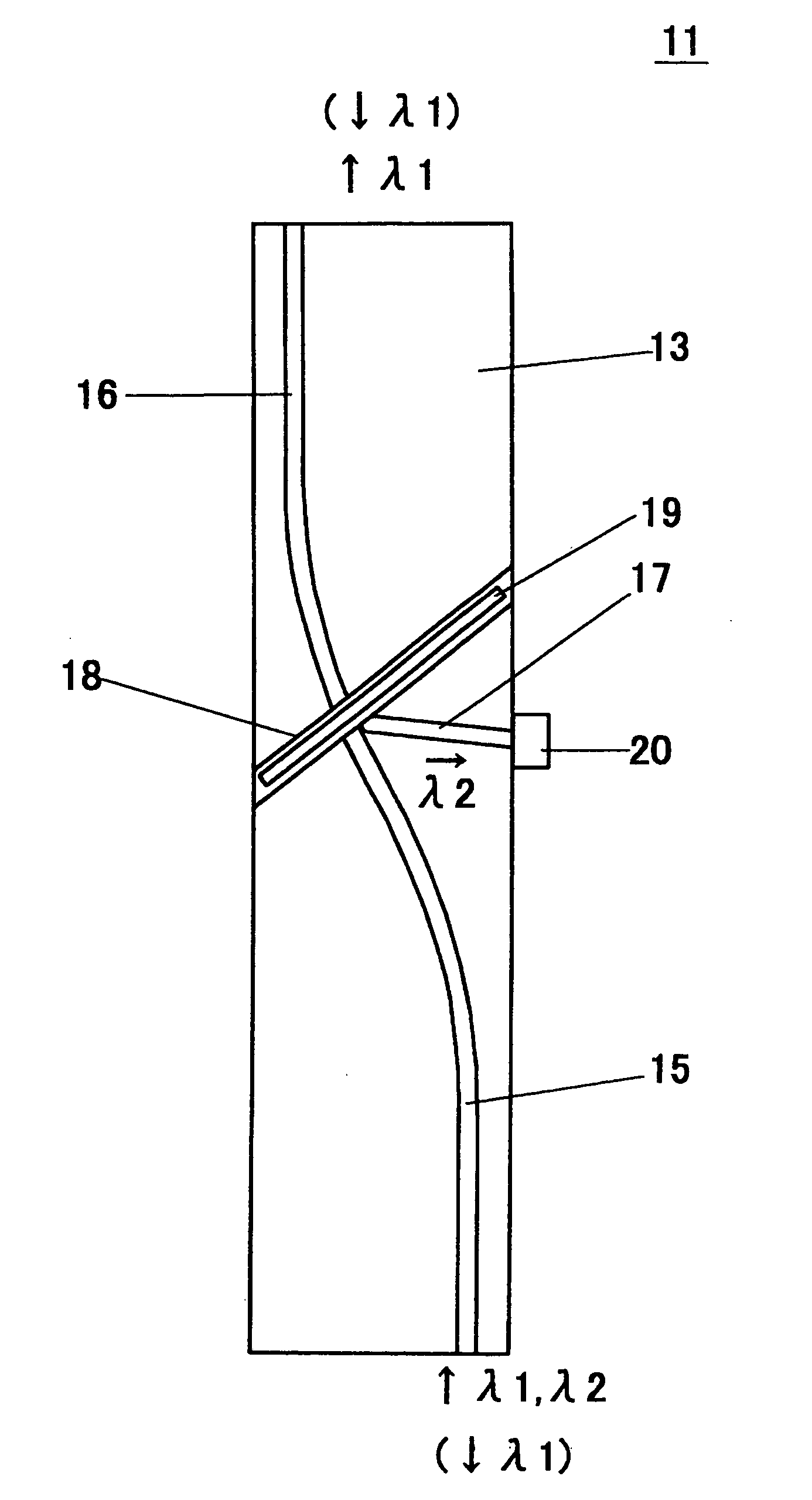
[0051]FIG. 6 is a perspective view showing an optical multiplexer / demultiplexer (optical waveguide) 11 according to a first embodiment of the invention. FIG. 7 is a plan view of the optical multiplexer / demultiplexer 11 shown without an upper cladding layer 21. In this optical multiplexer / demultiplexer 11, a lower cladding layer 13 in tabular form is formed on a substrate 12. Three cores 15, 16, 17 are formed in a core groove 14 formed in the surface of the lower cladding layer 13. The core 15 (first core) and the core 16 (third core) make up a curved main core. The ends of the main core (the end portions of the cores 15, 16 far from a thin-film filter 19 described later) reach the two end surfaces of the lower cladding layer 13. At the end portions of the lower cladding layer 13, the end portions of the cores 15, 16 are linearly formed and extend in parallel to the length of the lower cladding layer 13. The central portion of the main core is curved in the sha...
second embodiment
[0072] Second Embodiment
[0073]FIG. 13 is a plan view showing an optical multiplexer / demultiplexer 25 according to a second embodiment of the invention. The upper cladding layer 21 is not shown in this drawing and other subsequent drawings. In this optical multiplexer / demultiplexer 25, the core 16 in the first embodiment is not included, and a thin-film filter 19 is attached to the end surface of the lower cladding layer 13. The light having the wavelength λ1 demultiplexed by the thin-film filter 19 is adapted to directly enter the optical fiber fitted in the alignment groove 24.
third embodiment
[0074] Third Embodiment
[0075]FIG. 14 is a perspective view showing an optical multiplexer / demultiplexer 26 according to a third embodiment of the invention, FIG. 15A a plan view of the optical multiplexer / demultiplexer 26 free of the upper cladding layer 21, and FIGS. 15B, 15C partly enlarged views of FIG. 15A. FIG. 16 is a partly enlarged view of the neighborhood of the core 17 in FIG. 15A. In this optical multiplexer / demultiplexer 26, a rectangular tabular lower cladding layer 13 is formed on the substrate 12. Three cores 15, 16, 17 are formed in the core groove 14 formed in the surface of the lower cladding layer 13. The core 15 (first core) and the core 16 (third core) make up a linear main core. The cores 15 and 16 are optically coupled to each other through a thin-film filter 19 therebetween. The outer end surfaces of the cores 15, 16 reach the end surfaces 13A, 13B, respectively, of the lower cladding layer 13.
[0076] One end surface of the core 17 (second core) is also in op...
PUM
 Abstract
Description
Claims
Application Information
 - R&D
- Intellectual Property
- Life Sciences
- Materials
- Tech Scout
- Unparalleled Data Quality
- Higher Quality Content
- 60% Fewer Hallucinations
Browse by: Latest US Patents, China's latest patents, Technical Efficacy Thesaurus, Application Domain, Technology Topic, Popular Technical Reports.
© 2025 PatSnap. All rights reserved.Legal|Privacy policy|Modern Slavery Act Transparency Statement|Sitemap|About US| Contact US: help@patsnap.com


