Optical multiplexer/demultiplexer, optical integrated circuit and light transceiver using the same

a technology of optical integrated circuits and light transceivers, applied in the direction of optical elements, semiconductor lasers, instruments, etc., can solve the problems of communication interference, increase the light leakage from the core, and the inability to achieve high isolation and a smaller waveguide size, and achieve small polarization dependence, high isolation characteristic, and reduced size

Inactive Publication Date: 2006-06-20
ORMON CORP
View PDF24 Cites 6 Cited by
  • Summary
  • Abstract
  • Description
  • Claims
  • Application Information

AI Technical Summary

Benefits of technology

[0010]This invention has been achieved in view of the technical problems described above, and the object thereof is to provide an optical multiplexer / demultiplexer, an optical integrated circuit and a light transceiver using the same, which are high in isolation characteristic, small in polarization dependency and can be reduced in size.

Problems solved by technology

The light of the wavelength λ1 that has circumvented into the core 6 constitutes a noise in the core 6 or causes a signal loss in the core 3, thereby posing the problem of a communication interference.
An excessively increased radius of curvature of the core, however, would increase the light leakage from the core.
In the conventional optical multiplexer / demultiplexer 1, therefore, a high isolation and a smaller size of the waveguide cannot be attained at the same time, and it is impossible to produce a small optical multiplexer / demultiplexer having a high isolation characteristic.
Also, an increased waveguide size to secure a high isolation increases the signal loss due to the material loss of the core.

Method used


Image

  • Optical multiplexer/demultiplexer, optical integrated circuit and light transceiver using the same
  • Optical multiplexer/demultiplexer, optical integrated circuit and light transceiver using the same
  • Optical multiplexer/demultiplexer, optical integrated circuit and light transceiver using the same

Examples


first embodiment

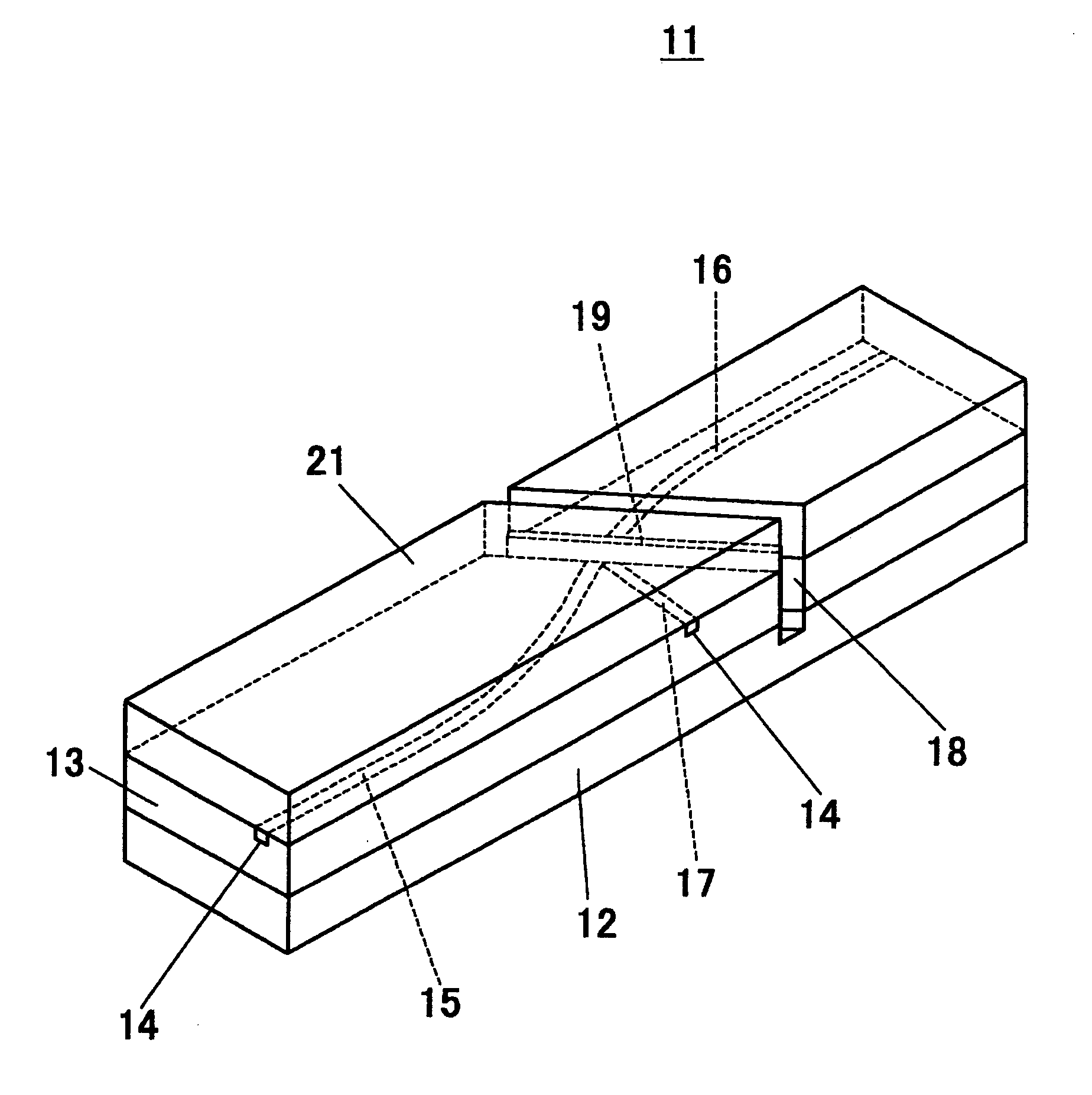
[0049]FIG. 6 is a perspective view showing an optical multiplexer / demultiplexer (optical waveguide) 11 according to a first embodiment of the invention. FIG. 7 is a plan view of the optical multiplexer / demultiplexer 11 shown without an upper cladding layer 21. In this optical multiplexer / demultiplexer 11, a lower cladding layer 13 in tabular form is formed on a substrate 12. Three cores 15, 16, 17 are formed in a core groove 14 formed in the surface of the lower cladding layer 13. The core 15 (first core) and the core 16 (third core) make up a curved main core. The ends of the main core (the end portions of the cores 15, 16 far from a thin-film filter 19 described later) reach the two end surfaces of the lower cladding layer 13. At the end portions of the lower cladding layer 13, the end portions of the cores 15, 16 are linearly formed and extend in parallel to the length of the lower cladding layer 13. The central portion of the main core is curved in the shape of S. A slit 18 is c...

second embodiment

[0070]FIG. 13 is a plan view showing an optical multiplexer / demultiplexer 25 according to a second embodiment of the invention. The upper cladding layer 21 is not shown in this drawing and other subsequent drawings. In this optical multiplexer / demultiplexer 25, the core 16 in the first embodiment is not included, and a thin-film filter 19 is attached to the end surface of the lower cladding layer 13. The light having the wavelength λ1 demultiplexed by the thin-film filter 19 is adapted to directly enter the optical fiber fitted in the alignment groove 24.

third embodiment

[0071]FIG. 14 is a perspective view showing an optical multiplexer / demultiplexer 26 according to a third embodiment of the invention, FIG. 15A a plan view of the optical multiplexer / demultiplexer 26 free of the upper cladding layer 21, and FIGS. 15B, 15C partly enlarged views of FIG. 15A. FIG. 16 is a partly enlarged view of the neighborhood of the core 17 in FIG. 15A. In this optical multiplexer / demultiplexer 26, a rectangular tabular lower cladding layer 13 is formed on the substrate 12. Three cores 15, 16, 17 are formed in the core groove 14 formed in the surface of the lower cladding layer 13. The core 15 (first core) and the core 16 (third core) make up a linear main core. The cores 15 and 16 are optically coupled to each other through a thin-film filter 19 therebetween. The outer end surfaces of the cores 15, 16 reach the end surfaces 13A, 13B, respectively, of the lower cladding layer 13.

[0072]One end surface of the core 17 (second core) is also in opposed relation to the thi...


PUM


Abstract

An optical multiplexer / demultiplexer having a high isolation characteristic, a small polarization dependency and capable of being reduced in size is disclosed. An end portion of a core and an end portion of a core are arranged in opposed relation to each other with a thin-film filter interposed therebetween. The end portion of the core far from the filter and the end portion of the core far from the filter are arranged in substantially parallel to each other. The core is arranged in such a manner as to branch from the filter-side end portion of the core and to be optically coupled with the core. The end portion of the core near to the filter and the end portion of the core near to the filter are curved. The end portion of the core near to the filter is curved in a manner protruded toward the core. The end portion of each of the core and the core far from the filter reaches an end of an optical waveguide, and the end portion of the core far from the filter reaches a side of the optical waveguide.

Description

BACKGROUND OF THE INVENTION[0001]1. Field of the Invention[0002]The present invention relates to an optical multiplexer / demultiplexer, an optical integrated circuit and a light transceiver using the same.[0003]2. Description of the Prior Art[0004]FIG. 1 is a plan view showing the structure of a conventional optical multiplexer / demultiplexer. In this optical multiplexer / demultiplexer 1, a main core including a core 3 and a core 4 is formed on a tabular cladding layer 2. One end of the core 3 and one end of the core 4 are optically connected to each other through a slit 5 cut in the cladding layer 2. The ends of the main core are linear in shape, and the central portion of the main core is curved in the shape of S. The slit 5 is formed in the curved portion of the main core. Also, a core 6 branching from the core 3 at the position of the slit 5 is formed on the same side as the core 3. A thin-film filter 7 is inserted in the slit 5.[0005]In this optical multiplexer / demultiplexer 1, as...

Claims


Application Information

Patent Timeline
Patent Type & Authority Patents(United States)
IPC IPC(8): G02B6/26G02B6/28G02B6/12G02B6/30G02B6/125G02B6/293G02B6/42H01L31/0232H01S5/022
CPCG02B6/12007G02B6/125G02B6/4246G02B6/2938G02B6/29361G02B2006/12116G02B2006/12109G02B6/12G02B6/28G02B6/293
Inventor HIGUCHI, MASAYOSHIHOSOKAWA, HAYAMIFUJIWARA, HIROYUKIHAYAMIZU, KAZUYUKIKOMURA, YOSHIYUKIENAMI, AKIRA
Owner ORMON CORP
Why Eureka
Try Eureka