
Image forming device

a technology of forming device and photoconductive drum, which is applied in the direction of optics, electrographic process apparatus, instruments, etc., can solve the problems of unevenness in the image forming process, inability to adhere evenly to the electrostatic latent image carrier, and displacement of the positional relationship between the photoconductive drum and the developing sleeve, etc., to achieve accurate operation, simple structure, and simple operation

Inactive Publication Date: 2005-03-03
MURATA MASCH LTD
View PDF0 Cites 35 Cited by
  • Summary
  • Abstract
  • Description
  • Claims
  • Application Information

AI Technical Summary

Benefits of technology

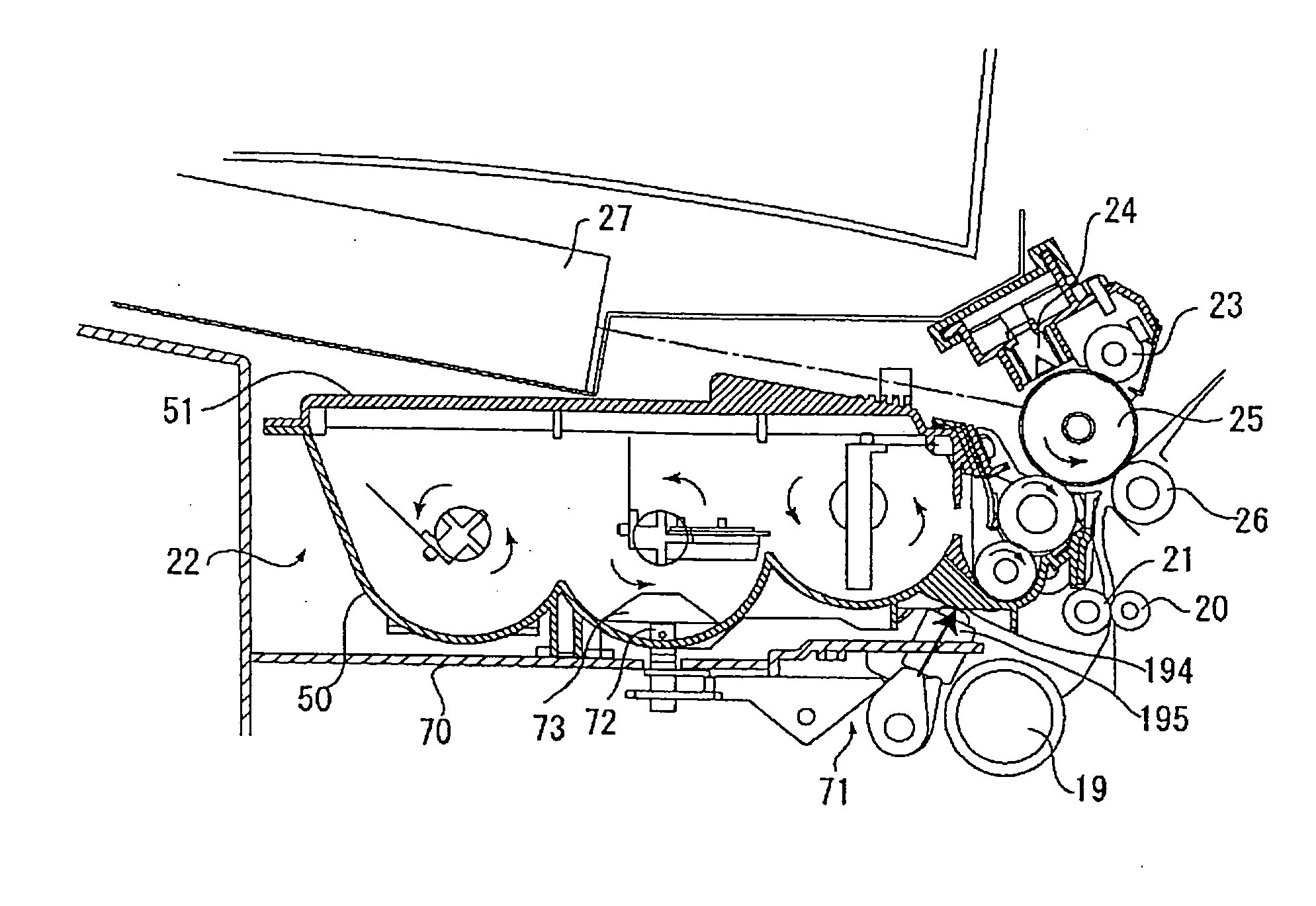
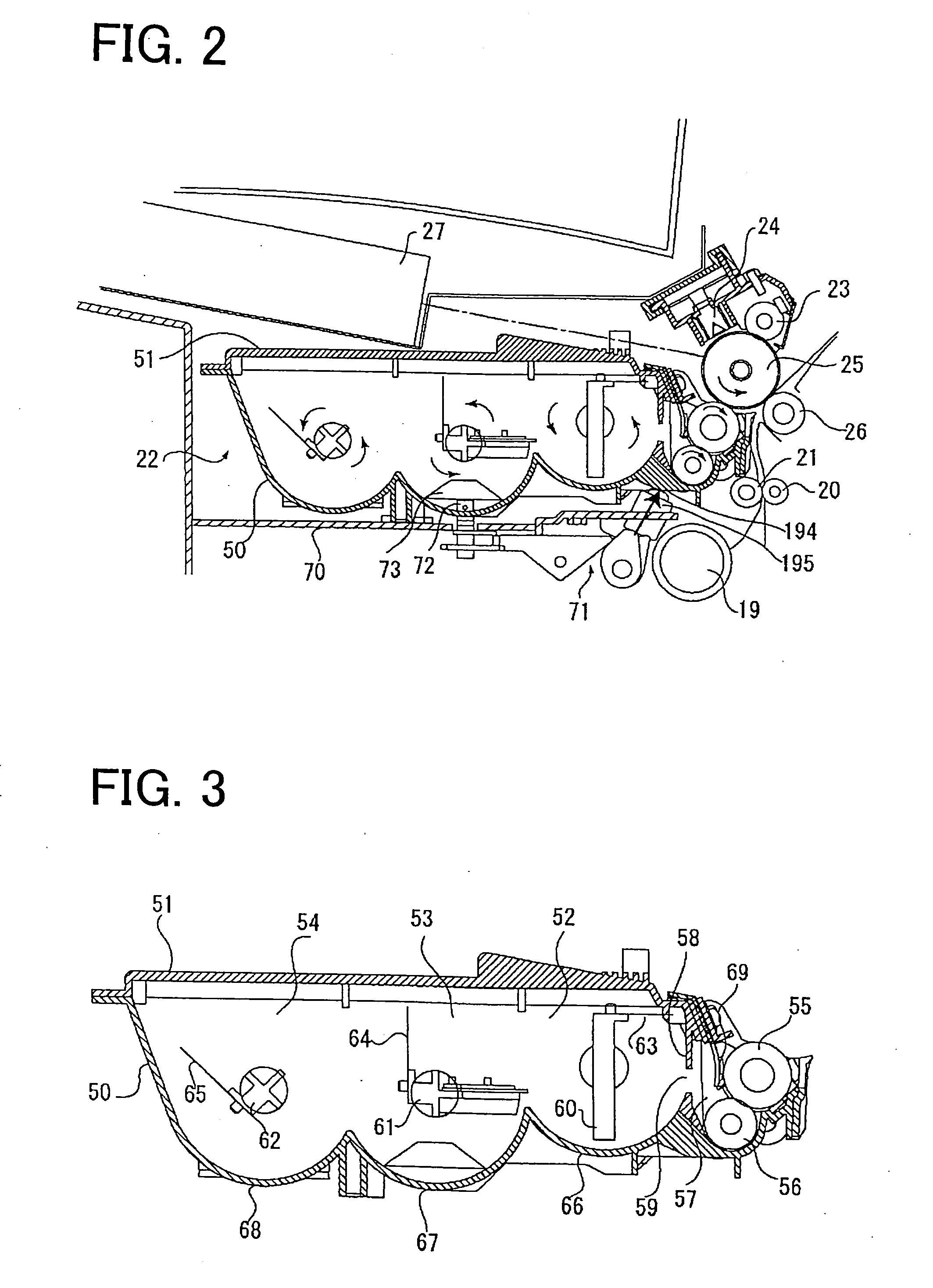
[0012] By the above-described configuration, the bottom surface of the developing unit is pressed by the pressing body provided on the main frame in the direction along the straight line orthogonal to the rotational center shaft of the electrostatic latent image carrier and the rotational center shaft of the developer carrier. Therefore, the developer carrier can be set under a state in which the developer carrier makes contact with the electrostatic latent image carrier accurately. Moreover, since the pressing body is held under a state in which the pressing body is pushing the bottom surface of the developing unit, the pressing body can be held under a stable state.
[0013] The operating unit includes a rotational shaft supported on the main frame and a cam member fixed on the rotational shaft. Accordingly, the operating unit can be operated accurately by a simple structure. Furthermore, the cam member, which has been operated once, holds the pressing body under a state in which the cam member is sandwiched between the main frame and the pressing body. As a result, the pressing body can be held without providing another mechanism for holding the cam member. Moreover, by fixing a gripper to be swung manually on one end part of the rotational shaft, the developing unit can be positioned by a simple operation.
[0014] According to an aspect of the present invention, the pressing body, which presses the bottom surface of the developing unit, includes a plurality of acting units which make point contacts with the developing unit along a flat plane including the rotational center shaft of the electrostatic latent image carrier and the rotational center shaft of the developer carrier. Accordingly, the developing unit can be pressed by a uniform pressing force. Therefore, the developer carrier can be positioned accurately with respect to the electrostatic latent image carrier, and the developer carrier can make contact with the electrostatic latent image carrier uniformly. Furthermore, the plurality of the acting units are arranged to be symmetrical with respect to a straight line along the plane that passes through a center of a contact range of the developer carrier and the electrostatic latent image carrier. Accordingly, the developing unit can be pressed evenly at left and right. Moreover, a part of the acting units that makes contact with the developing unit is formed hemispheric. Accordingly, the acting units can make contact with the developing unit stably. In addition, a part of the developing unit that makes contact with the acting units is formed in a cross-shaped rib. Accordingly, the acting units and the developing unit can be contacted with one another stably and the strength of the part of the developing unit that makes contact with the acting units can be improved.
[0015] According to an aspect of the present invention, the pressing body, which presses the bottom surface of the developing unit, includes a plurality of acting members and a plurality of urging units. The acting members make contact with the developing unit and can be slid in the direction of the straight line. The urging units urge each of the acting members so as to press the developing unit. Accordingly, the urging units acting as a buffer, can adjust a subtle difference of the pressing force between the developing unit and each of the acting members. As a result, the developing unit can be pressed from the bottom surface under a more stable state. In addition, the urging units include an adjusting unit for adjusting the pressing force of the acting members with respect to the developing unit. Accordingly, the contacting state in the contact range between the electrostatic latent image carrier and the developer carrier can be adjusted subtly.
[0016] Moreover, in response to the movement of the operating unit which operates to slide the pressing body, a remaining amount detector is transferred between a receded position and an operational position. Therefore, in response to the positioning of the developing unit, the remaining amount detector can be set easily and reliably. The receded position is a position where the remaining amount detector is receded from a range where the developing unit passes through when the developing unit is inserted or removed. Therefore, the developing unit can be inserted or removed easily without being interfered with by the remaining amount detector. Furthermore, by forming the operating unit and a transferring unit by a first cam member and a second cam member fixed on a rotational shaft, the operating unit and the transferring unit can be moved in response to the movement of one another easily and reliably by rotating the rotational shaft. In addition, the remaining amount detector is supported on the main frame, and transferred by being swung. Accordingly, the remaining amount detector can be set reliably at the receded position and the operational position. Moreover, by inserting the remaining amount detector into a remaining amount detecting part formed on the developer and setting the remaining amount detector at the operational position, the remaining amount detector can be set under a stable state with respect to the developing unit.

Problems solved by technology

However, if the developing unit is not positioned properly with respect to the electrostatic latent image carrier, the developer is not adhered evenly on the electrostatic latent image carrier and unevenness is generated in the image forming process.
However, since a pressure force for the photoconductive drum is applied to the pressure rollers, if a positional relationship between the regulatory members and the pressure rollers is not set precisely, a positional relationship between the photoconductive drum and the developing sleeve is displaced and the developer cannot be moved evenly from the developing sleeve to the photoconductive drum.
Moreover, according to the method to press the pressure rollers directly and to contact the pressure rollers against a surface of the photoconductive drum, an excessive force is applied to the pressure rollers and there are cases in which the positioning cannot be carried out properly.
However, it is difficult to insert the developing unit from a lateral side.
However, if there is a gap, after the developing unit is inserted, the developing unit jounces and cannot be positioned accurately.
However, an available volume in the developing unit is reduced by a volume of the concave groove and an amount of the toner that can be accumulated becomes small.
In the fourth conventional image forming device, since the magnetic toner sensor makes contact with an outer surface of the container, an optical sensor cannot be used.

Method used


Image

  • Image forming device
  • Image forming device
  • Image forming device

Examples


Embodiment Construction

[0063] An embodiment of the present invention will be described. The embodiment to be described below is a preferable specific example for implementing the present invention. Therefore, there are various technical limitations in the description. However, unless explicitly stated in the flowing description to limit the present invention, the present invention shall not be limited to the embodiments.

[0064] (Entire Structure of an Image Forming Device)

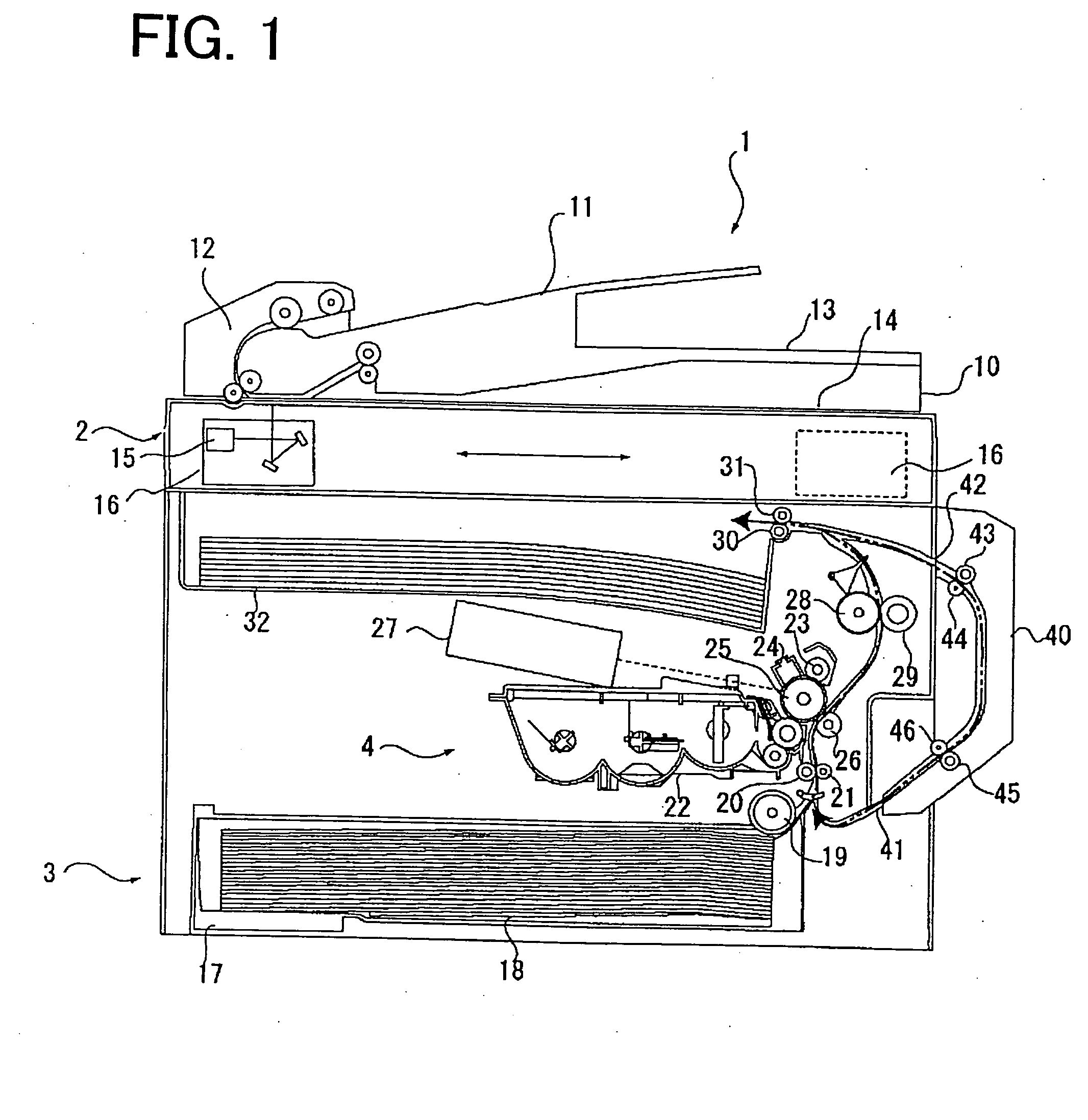
[0065]FIG. 1 is a schematic cross-sectional view of the entire image forming device according to an embodiment of the present invention. In an upper part of an image forming device 1, a document scanning unit 2 is disposed. In a lower part of the image forming device 1, a paper feed unit 3 and a printing unit 4 are disposed in this order from a bottom surface.

[0066] In the document scanning unit 2, an original document placed on a document tray 11 is transported to a scanning position by a document transportation device 12 and discharg...


PUM


Abstract

An image forming device includes an electrostatic latent image carrier on which an electrostatic latent image is formed, a main frame which supports the electrostatic latent image carrier, and a developing unit which is inserted removably in the main frame. The developing unit includes a developer carrier which supplies a developer to the electrostatic latent image carrier and a replenish chamber which replenishes the developer to the developer carrier. The image forming device also includes a pressing body which is provided on the main frame and is slidable in a direction along a straight line orthogonal to a rotational center shaft of the electrostatic latent image carrier and a rotational center shaft of the developer carrier, and an operating unit which operates the pressing body to press a bottom surface of the developing unit by sliding the pressing body in a direction of the straight line and to hold the pressing body so that the developer carrier is maintained under a state making contact with the electrostatic latent image carrier.

Description

BACKGROUND OF THE INVENTION [0001] 1. Field of the Invention [0002] The present invention relates to an image forming device such as a copy machine, a printer and a facsimile machine in which a removable developing unit is used for adhering a developer on an electrostatic latent image and developing the electrostatic latent image. [0003] 2. Description of the Related Art [0004] In an image forming device, when carrying out an image forming process by adhering a developer (toner) onto an electrostatic latent image carrier on which an electrostatic latent image is formed, a remaining amount of the developer decreases with the use of the developer in the image forming process. Therefore, it is necessary to replenish the developer as needed. Thus, the developing unit is formed capable of being inserted and removed with respect to the image forming device. When necessary, the developing unit is removed from the image forming device and the developer is replenished or the developing unit ...

Claims


Application Information

Patent Timeline
Patent Type & Authority Applications(United States)
IPC IPC(8): G03G15/08
CPCG03G15/0813G03G2221/1654G03G2221/163
Inventor NAKANO, TAKASHIKAWAI, HIDEAKI
Owner MURATA MASCH LTD
Learn More