Burner apparatus

a burner and cylinder technology, applied in the direction of combustion control, combustion types, combustion using lumps and pulverulent fuels, etc., can solve the problems of unburned fuel, high co emissions, and incomplete mixing of hot exhaust gases

Inactive Publication Date: 2005-03-03
L & S CRYOGENICS
View PDF5 Cites 23 Cited by
  • Summary
  • Abstract
  • Description
  • Claims
  • Application Information

AI Technical Summary

Problems solved by technology

A typical problem of prior art burner apparatuses used in direct fired nitrogen vaporizers is that there is incomplete mixing of the hot exhaust gases and the so-called secondary air that allows hot and cold areas to form in the heat exchanger.
Additionally, the prior art burner apparatuses have suffered from the problem that there is a long flame front that can impinge directly on the combustion chamber and tube bundle in the exchanger, thereby shortening the life of these components.
Additionally, it is not infrequent that there is incomplete combustion because of the large volume of fuel that is being sprayed from such a small area, i.e., a burner nozzle, resulting in smoke, high emissions of CO, and unburned fuel.

Method used


Image

  • Burner apparatus
  • Burner apparatus
  • Burner apparatus

Examples


Embodiment Construction

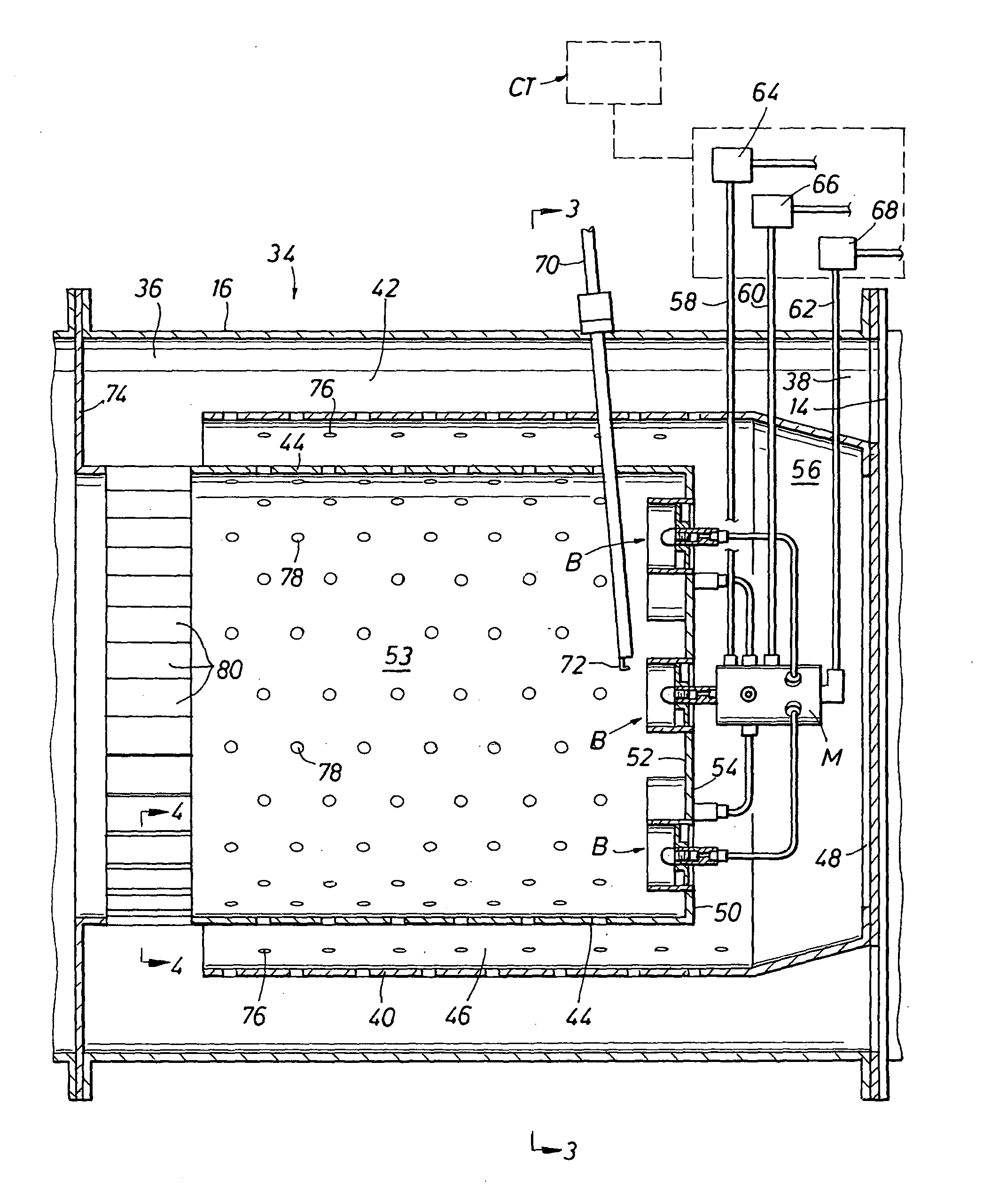
[0017] While the invention will be described with reference to a direct fired nitrogen vaporizer, it is to be understood that it is not so limited. Thus, the burner apparatus of the present invention can be used in any system where there is a need to vaporize a liquified gas stream or for that matter, to vaporize relatively low boiling liquids.

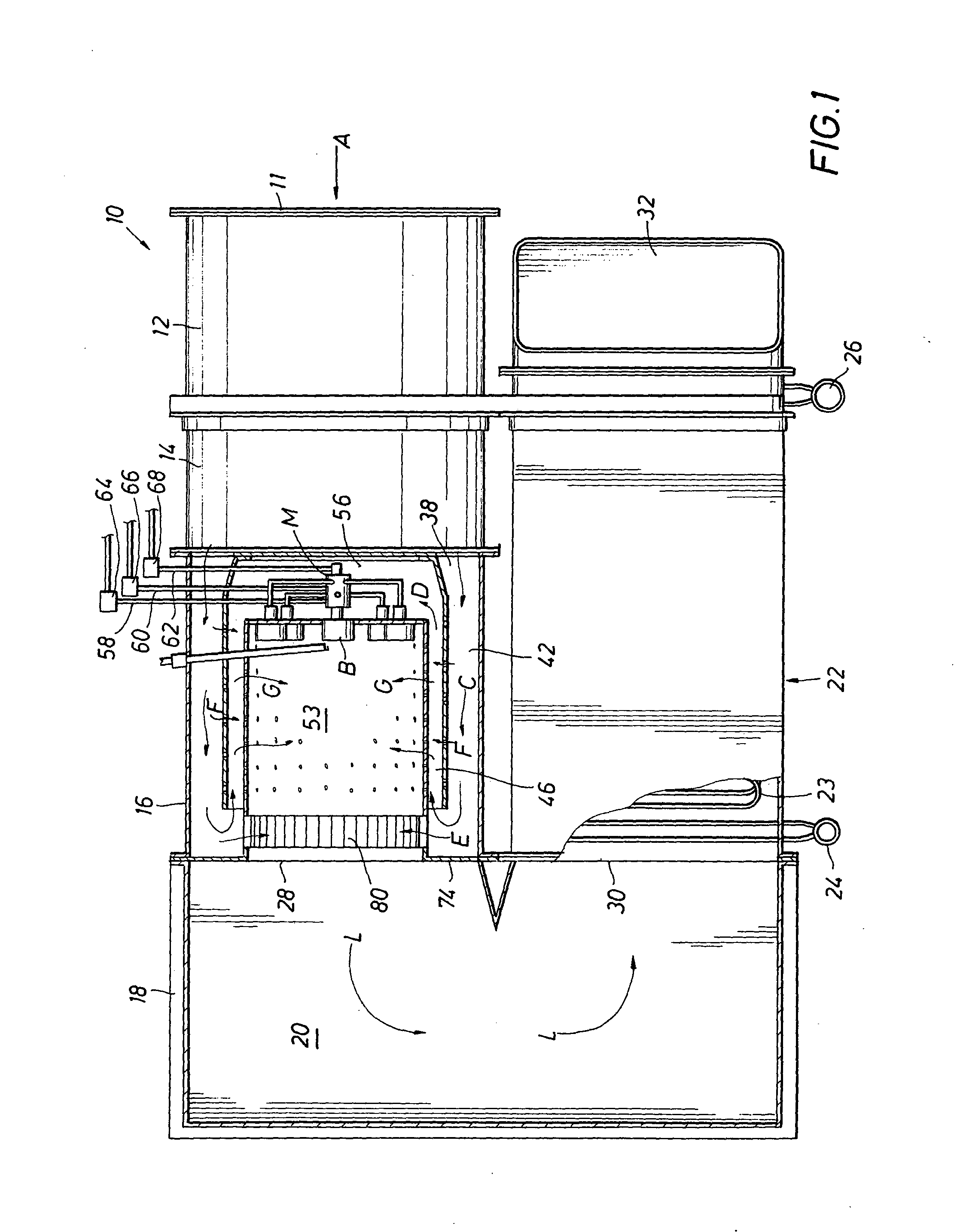
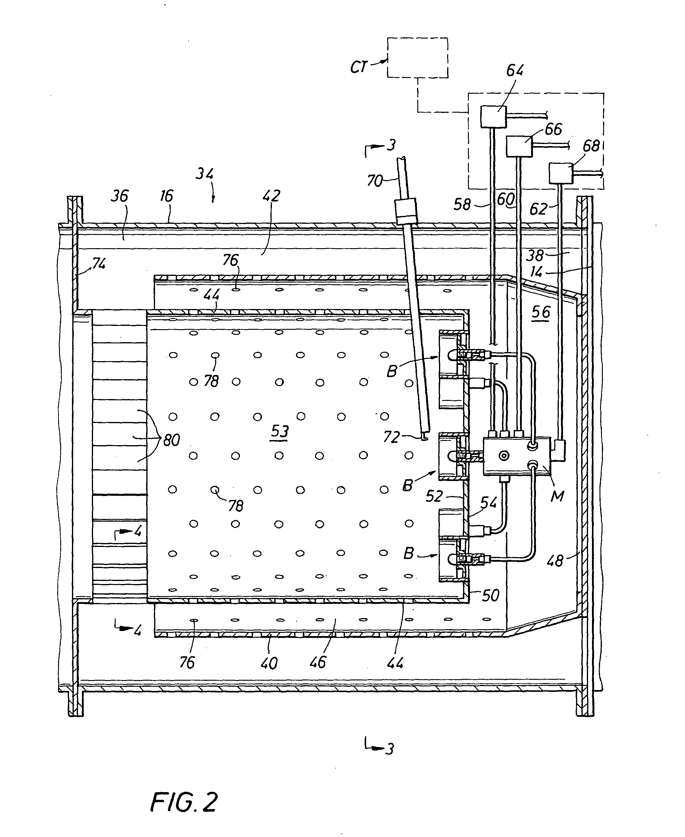
[0018] Referring now to FIG. 1, a direct fired nitrogen vaporizer, shown generally as 10 is shown. Vaporizer 10 comprises a fan housing 12 having a fan (not shown disposed therein) there being an air intake 11 in fan housing 12. A bolt type, flange connector 14 connects fan housing 12 to a burner apparatus housing 16. Housing 16 is in turn connected to a plenum box 18 providing a plenum 20. Plenum 20 opens into a tube / shell type exchanger 22. In exchanger 22, liquid nitrogen or other liquified gas, which is to be heated / vaporized, enters via inlet 24 and passes through a series of tubes 23 interiorly of exchanger 22, vaporized nitrogen exitin...


PUM


Abstract

A burner apparatus comprising housing defining a chamber and having an air inlet, a peripherally extending baffle disposed in the housing, a first peripherally extending flow passage being formed between the housing and the baffle, the first flow passage being in open communication with the air inlet, a peripherally extending combustion liner disposed inwardly of the baffle, a second peripherally extending flow passage being formed between the liner and the baffle, the second flow passage being in open communication with the first passage, a reversing diverter disposed in the chamber and positioned to direct air flowing from the first flow passage into the second flow passage, a burner assembly mounting plate disposed in the liner and having a first side and a second side, the mounting plate and the liner at least partially defining a burner barrel on the first side of the mounting plate, at least one burner assembly mounted on the burner mounting plate and a plenum on the second side of the mounting plate that is in open communication with the second flow passage.

Description

BACKGROUND OF THE INVENTION [0001] 1. Field of the Invention [0002] The present invention relates to a burner apparatus and, more particularly, to a burner apparatus that can be used in direct fired nitrogen vaporizers. [0003] 2. Description of the Prior Art [0004] Direct fired nitrogen vaporizers have been used, for example, to supply nitrogen for use in various oil and gas production operations. Such vaporizers commonly burn diesel or similar liquid fuels. In a typical direct fired nitrogen vaporizer, the hot combustion gas generated by burning the liquid fuel is used to heat and vaporize a high pressured liquid nitrogen stream. [0005] A typical direct fired nitrogen vaporizer includes a burner barrel wherein the liquid fuel is combined with air and is burned, a plurality of burner assemblies positioned in an end wall of the burner barrel, a fan that supplies air to the burner barrel, and a nitrogen tube assembly, similar to a tube / bundle heat exchanger, through which a high press...

Claims


Application Information

Patent Timeline
Patent Type & Authority Applications(United States)
IPC IPC(8): F23D11/00F23D11/10F23D11/26F23D11/44F23D23/00F23D99/00
CPCF23D11/007F23D11/107F23D11/26F23N2037/02F23D23/00F23D99/006F23D2900/11002F23D11/44F23D91/04F23N2237/02
Inventor STEINER, MICHAEL C.
Owner L & S CRYOGENICS
Why Eureka
Try Eureka