
Method and apparatus for power flow management in electro-mechanical transmissions

Active Publication Date: 2005-03-03
THE TIMKEN CO
View PDF6 Cites 59 Cited by
  • Summary
  • Abstract
  • Description
  • Claims
  • Application Information

AI Technical Summary

Benefits of technology

The objective of present invention is to provide a simple, compact and low cost solution to continuously variable transmissions and to vehicle hybridization. Another objective is to eliminate internal power circulation and provide smooth, non-interruptive shifting in speed, torque and power between regime or mode changes.
One of important features of the invention is the high transmission efficiency over wide speed ratio range, from very low speed, down to vehicle stop, up to very high speed as in highway operation.
The transmission of current invention provides smooth reconfigurations of power paths. These reconfigurations, also called regime or mode shafting or change, are continuous in speed, torque and power.

Problems solved by technology

Speed ratio change is often associated with interruptions in both speed and torque.
The major disadvantage of stepwise transmission is system efficiency, since the engine cannot always operate at its most efficiency speed.
For the same reason, pollution is also a problem for a vehicle with a stepwise transmission.
Hydrostatic drives are noisy and have low efficiency.
Friction or traction drives are more efficient, but they are less rugged for handling large torque loads.
In addition, many the traction drives are usually quite heavy and costly to manufacture.
The THS system is now in limited production.
Internal power circulation generates heat and power loss and offsets the efficiency benefit otherwise provided by the transmission.
For this reason, the effective speed ratio range is limited.
As with single planetary unit, a two-node system also suffers from the internal power circulation problem.
The constructions of these transmissions are complex.
Shifting between different modes presents an interesting challenge.

Method used


Image

  • Method and apparatus for power flow management in electro-mechanical transmissions
  • Method and apparatus for power flow management in electro-mechanical transmissions
  • Method and apparatus for power flow management in electro-mechanical transmissions

Examples


Embodiment Construction

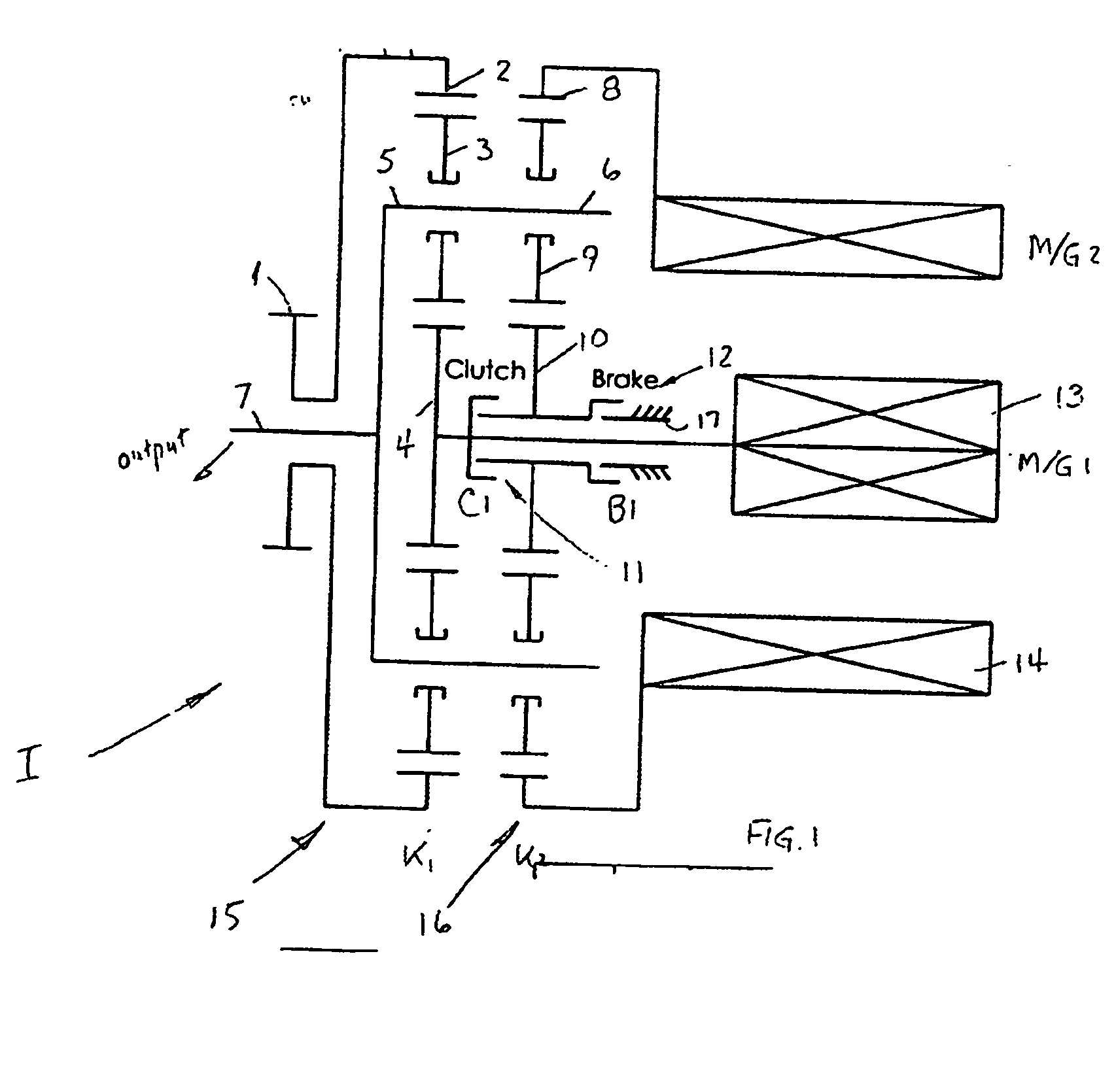
Referring to FIG. 1, an electric hybrid transmission I comprises first and second planetary trains 15, 16 each having a first and second sun member 4, 10, a first and second ring member 2, 8, a first and second plurality of planets 3, 9 and a first and second planet carrier 5, 6. An input means I is directly connected to the first ring member 2. An output means 7 is connected to the first planet carrier 5 and to the second planet carrier 6. A first electric machine 13 is connected to the first sun member 4, and a second electric machine 14 is connected to the second ring member 8. A locking clutch 11 selectively connects the first sun member 4 of the first planetary train 15 to the second sun member 10 of the second planetary train 16. A brake 12 selectively grounds the second sun member 10 of the second planetary train 16 to a fixed, non-rotational member 17 of the transmission I.

The first electric machine 13 is connected to the second electric machine 14 through a power-regulat...


PUM


Abstract

A method for power management in an electro-mechanical power-split infinitely variable transmission (eVT) designed to operated within a designated speed ratio range for vehicular applications. The eVT is comprised of an input shaft coupled to the output shaft of a drive engine to receive power, a drive shaft, two electric machines, and a pair of planetary trains each having a sun member, a ring member, a set of planetary members, and a planet carrier. The eVT further contains one or more torque transfer devices to connect or disconnect members of the planetary trains for transferring torque. The drive shaft is coupled with a final drive of a vehicle for delivering or recapturing power to or from the vehicle drive wheels. The two electric machines are interconnected electronically via a power control unit and are coupled respectively with members of the planetary train. The method of power management in the eVT is selected based on the current speed and torque of the input and drive shafts, and upon the desired operating parameters.

Description

BACKGROUND OF THE INVENTION A transmission is an important part of vehicle power train. The primary function of a transmission is to regulate speed and torque to meet the operator demands for speed and acceleration. The major requirements for transmissions are speed ratio range, torque capacity, efficiencies, including transmission and system efficiencies, weight and cost. There are two types of transmissions: stepwise and step-less. Stepwise transmissions, using multiple gear sets and clutching devices, are quite popular. The speed ratio change is accomplished in discrete steps. Speed ratio change is often associated with interruptions in both speed and torque. The output speed variation between two speed ratios is realized by varying the input speed. The major disadvantage of stepwise transmission is system efficiency, since the engine cannot always operate at its most efficiency speed. For the same reason, pollution is also a problem for a vehicle with a stepwise transmission. ...

Claims


Application Information

Patent Timeline
IPC IPC(8): B60K1/02B60K6/365B60K6/445B60K6/543B60L50/16B60W10/08B60W10/10B60W20/00F16H3/72
CPCB60K1/02B60K6/365B60K6/445B60K6/543B60W10/08B60W10/10Y10T477/337F16H3/727F16H3/728F16H2037/102F16H2200/2007Y02T10/6239B60W20/00Y02T10/62B60W20/10
Inventor AI, XIAOLANANDERSON, SCOTT
Owner THE TIMKEN CO
Learn More