Intravenous injection device

a technology of intravenous injection and injection device, which is applied in the direction of ultrasonic/sonic/infrasonic image/data processing, diagnostic recording/measuring, ultrasonic/sonic/infrasonic diagnostics, etc., can solve the problems of increasing the risk, increasing the workload, and pain for the examinee, so as to achieve the effect of improving accuracy and automation

Inactive Publication Date: 2005-03-03
MICRO-STAR INTERNATIONAL
View PDF9 Cites 5 Cited by
  • Summary
  • Abstract
  • Description
  • Claims
  • Application Information

AI Technical Summary

Benefits of technology

[0013] The present invention utilizes the pulse ultrasonic oscillator to measure the reflective signals to accumulate effective reflection according to the Doppler's effect in order to obtain the data on the depth of a vein and then uses the propeller to insert the syringe at a proper depth along the signal direction so that the precision and automation are both improved.

Problems solved by technology

In the case of the examinee being the fat or the infant, the task is made more difficult because their vein is not always easily found, meaning that the operators may have to repeatedly insert the needle until the proper position for injection is found.
That not only causes pain to the examinee but also raises the risk.
Therefore, it is difficult to distinguish the blood and soft tissues by using the reflective signals. FIG. 1 shows a conventional ultrasound probe detecting blood current.
However, it is required to select a vein with low current speed for blood test or injection, meaning that the Doppler shift effect is generally unobvious; added, it is difficult to distinguish the blood from neighboring soft tissues.
Furthermore, continuous ultrasonic detecting can only tell the operators whether there is a moving object but cannot provide any axial analysis, i.e. the depth of the moving object remains unknown.
Moreover, the syringe 73 is positioned so far from the probe 72 that it is not convenient for operators to hold them with two hands.

Method used


Image

  • Intravenous injection device
  • Intravenous injection device
  • Intravenous injection device

Examples


Embodiment Construction

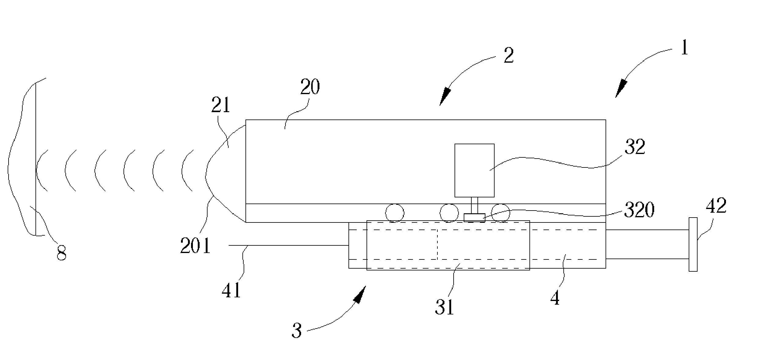
[0023] Please refer to FIG. 6 and FIG. 7; an intravenous injection device 1 according to the present invention includes a pedestal 2, a propeller 3 and a syringe 4.

[0024] The pedestal 2 includes a housing 20, a pulse ultrasound probe 21 contained in the housing 20, and a microprocessor 22. The end of the housing 20 toward the examinee is hereby defined as a front end 201. In order not to be interfered with, the probe 21 is installed at the front end 201. The probe 21 includes an oscillator 211 and a sensor 212. In the present embodiment, when the microprocessor 22 generates a command to the oscillator 211, the oscillator 211 oscillates, thereby generating pulse ultrasonic signals that it forwards. The signals are reflected by interfaces between different tissues and organs and then received by the sensor 212 to be converted into electrical signals to be output to the microprocessor 22.

[0025] Since the ultrasonic signals are pulse signals, after a period of time, the reflective vol...


PUM


Abstract

An intravenous injection device for detecting the position of a vein of an examinee includes a pedestal comprising a housing, a pulse ultrasound probe installed in front of the housing, and a microprocessor installed in the housing wherein the pulse ultrasound probe includes an oscillator for emitting a pulse ultrasonic signal toward the examinee along the direction of the housing and a sensor for receiving ultrasonic signals reflected by the examinee and converting the reflected signals into electric signals to output to the microprocessor, a propeller for moving the pedestal along the direction of the pulse ultrasonic signals, and a syringe connected to and conveyed by the propeller to move along the direction of the pulse ultrasonic signals.

Description

BACKGROUND OF INVENTION [0001] 1. Field of the Invention [0002] The invention relates to an intravenous injection device, and more particularly to an intravenous injection device utilizing an ultrasonic vein detector. [0003] 2. Description of the Prior Art [0004] Generally performed medical services such as endoscope operations or radiation tumor treatments are accompanied with objective data-gathering means such as X-ray scan or magnetic resonance imaging (MRI) in order to provide objective images to the operator in order to aid in the operation. [0005] On the other hand, blood tests and injections depend only on the experience of operators in selecting a proper position to insert the needle to extract a blood sample or inject medicine; no objective references are used. In the case of the examinee being the fat or the infant, the task is made more difficult because their vein is not always easily found, meaning that the operators may have to repeatedly insert the needle until the p...

Claims


Application Information

Patent Timeline
Patent Type & Authority Applications(United States)
IPC IPC(8): A61M5/00A61B8/06A61B8/08A61M5/178A61M5/32
CPCA61B5/489A61B8/0841A61B8/0833A61B8/06
Inventor WU, CHUNG-YUOLO, MENG-TSUNGCHANG, YI-CHUNG
Owner MICRO-STAR INTERNATIONAL
Why Eureka
Try Eureka