Drive-by-wire lawnmower

a lawnmower and drive-by-wire technology, applied in the direction of mechanical equipment, non-deflectable wheel steering, transportation and packaging, etc., can solve the problems of difficult time-consuming, difficult adjustment of the control and operation of the lawnmower, and the inability to adjust the mower while the mower is operating

Inactive Publication Date: 2005-03-10
TEXTRON INNOVATIONS
View PDF31 Cites 8 Cited by
  • Summary
  • Abstract
  • Description
  • Claims
  • Application Information

AI Technical Summary

Benefits of technology

[0017] Preferably, the second controller has a neutral position disposed between the left and right positions. Positioning of the second controller in the neutral position causes the second controller to not affect a rate at which each of the at least two wheels rotate. Even more preferably, the second controller is biased to the neutral position so that the second controller is positioned in the neutral position when no force is being applied to the second controller. Movement of the second controller from the neutral position toward the left and right positions causes the difference in the rate of rotation of the at least two wheels to increase in proportion to the movement of the second controller from the neutral position.
[0018] Optionally, but preferably, the second controller is selectively moveable between extreme left and extreme right positions. The extreme left and extreme right positions are disposed beyond the respective left

Problems solved by technology

While the use of mechanical linkages to control the operation of a typical riding lawn mower with hydraulically driven wheels has proved useful, the use of mechanical linkages has drawbacks.
For example, adjustments to the control and operation of the lawn mower can be difficult and time consuming.
Additionally, due to safety concerns about where a person adjusting the mechanical linkages needs to place their hands, some adjustments cannot be made while the mower is operating.
Therefore, the results of the adjustments of the mechanical linkages cannot be ascertained until after the mower is in op

Method used


Image

  • Drive-by-wire lawnmower
  • Drive-by-wire lawnmower
  • Drive-by-wire lawnmower

Examples


Embodiment Construction

[0033] The following description of the preferred embodiment(s) is merely exemplary in nature and is in no way intended to limit the invention, its application, or uses.

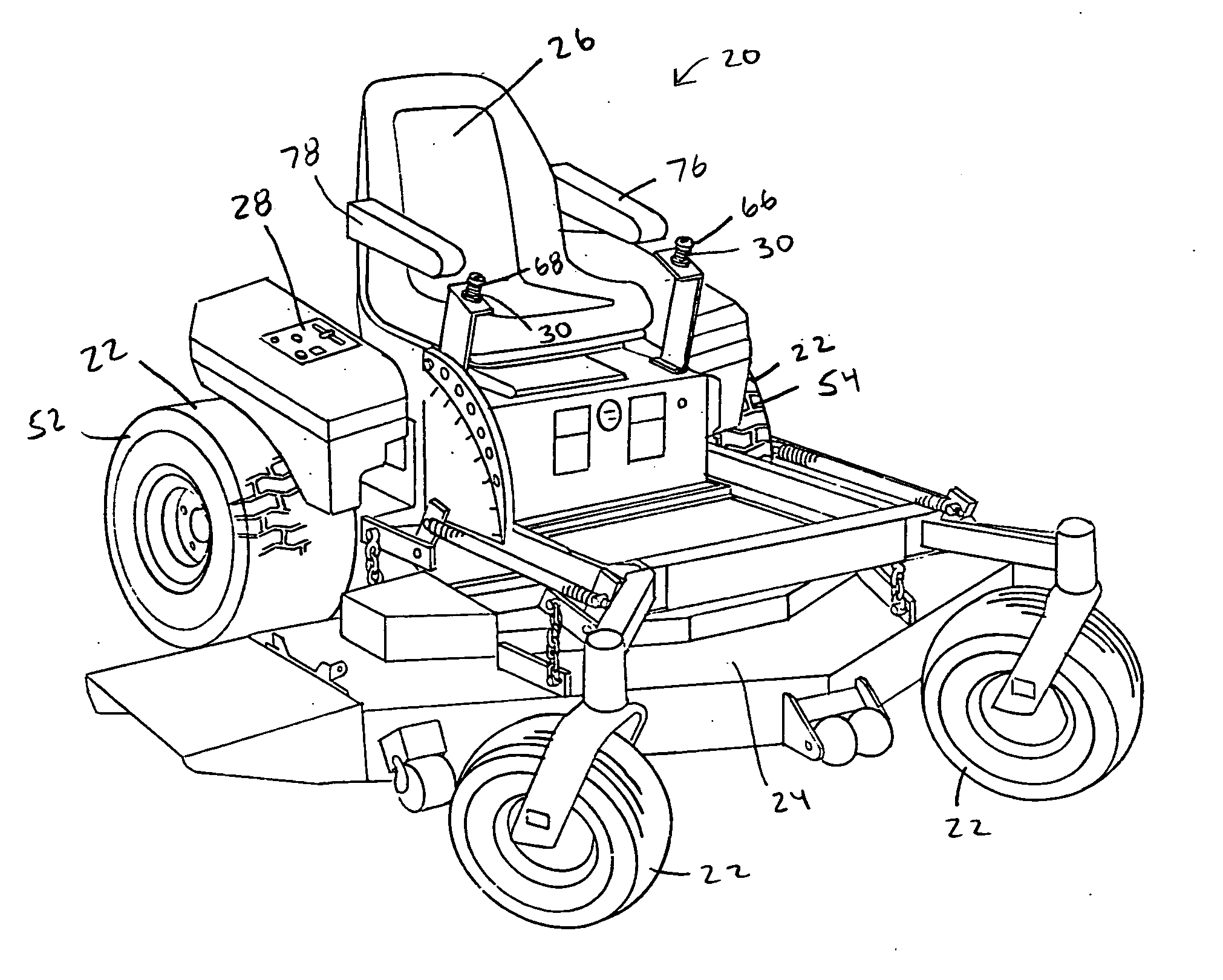
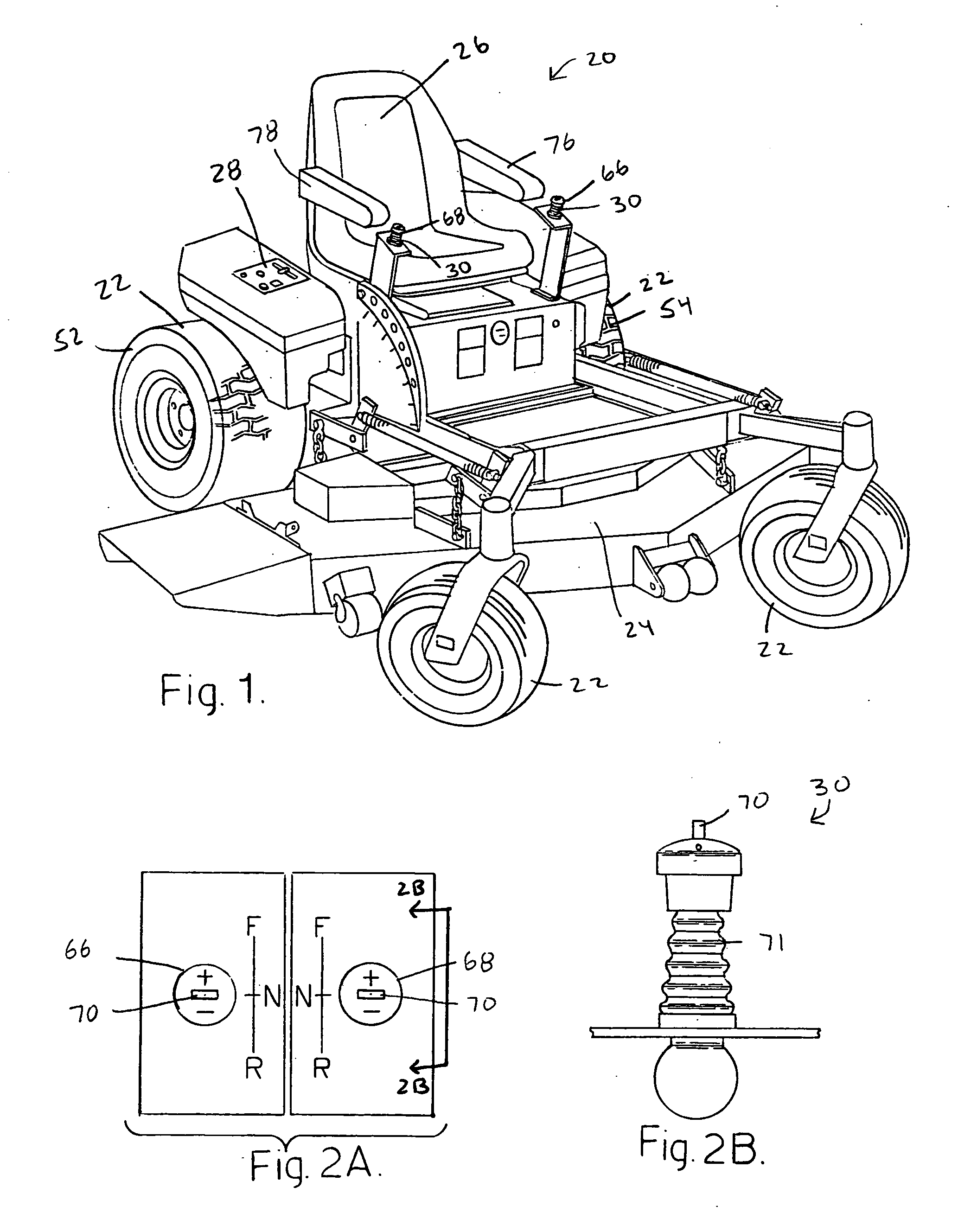
[0034] Referring to FIG. 1, there is shown a zero turning radius vehicle, in the form of drive-by-wire riding lawn mower 20, in accordance with a preferred embodiment of the present invention. While the zero turning radius vehicle is illustrated and described as being a drive-by-wire riding lawn mower 20, it should be understood that the principles of the present invention are applicable to other zero turning radius vehicles, including but not limited to skid steer loaders, other turf care vehicles, and the like. Zero turning radius vehicles are generally defined as vehicles having two or more wheels capable of independent bi-directional rotation so that the zero turning radius vehicle can perform counter steering operations. That is, the two or more independent wheels of a zero turning radius vehicle are capable of...


PUM


Abstract

The mower has at least two independently driven wheels that are each capable of bi-directional rotation. The at least two wheels are independently driven so that operation of the at least two wheels causes the at least two wheels to independently rotate which propels and steers the mower. A microprocessor controls the operation of the at least two wheels in accordance with signals received by the microprocessor. The mower has at least one controller. The at least one controller sends signals to the microprocessor that the microprocessor uses to control the operation of the at least two wheels. The operation of the at least one controller causes the at least two wheels to propel and steer the mower.

Description

CROSS-REFERENCE TO RELATED APPLICATIONS [0001] This application is a divisional of U.S. patent application Ser. No. 10 / 017,473 filed on Dec. 14, 2001. The disclosure of the above application is incorporated herein by reference.FIELD OF THE INVENTION [0002] The present invention relates to zero turning radius vehicles, such as turf care vehicles, skid steer loaders, and the like, and more specifically, to riding lawn mowers that are driven-by-wire. BACKGROUND OF THE INVENTION [0003] Riding lawn mowers come in a variety of sizes and configurations. The typical riding lawn mower has an internal combustion engine that provides power to propel the riding lawn mower. In some riding lawn mowers, the internal combustion engine is used to turn a hydraulic pump(s) that supplies a flow of hydraulic fluid that is used to drive wheels on the mower. The hydraulically driven wheels propel the mower. The speed at which the mower is propelled can be controlled by adjusting the rate of flow of the hy...

Claims


Application Information

Patent Timeline
IPC IPC(8): B62D11/00B62D11/04B62D11/18
CPCB60W2300/156B60Y2200/223Y10T477/68B62D11/04B62D11/003A01D34/006A01D34/64
Inventor WUERTZ, ROBERT M.BENSON, TERRANCE G.
Owner TEXTRON INNOVATIONS
Why Eureka
Try Eureka