
Electronic throttle ice break method and apparatus

a technology of electronic throttle and ice break, which is applied in the direction of engine controllers, mechanical equipment, machines/engines, etc., can solve problems affecting the performance of engines

Inactive Publication Date: 2005-03-10
GENERAL MOTORS COMPANY
View PDF6 Cites 7 Cited by
  • Summary
  • Abstract
  • Description
  • Claims
  • Application Information

AI Technical Summary

Benefits of technology

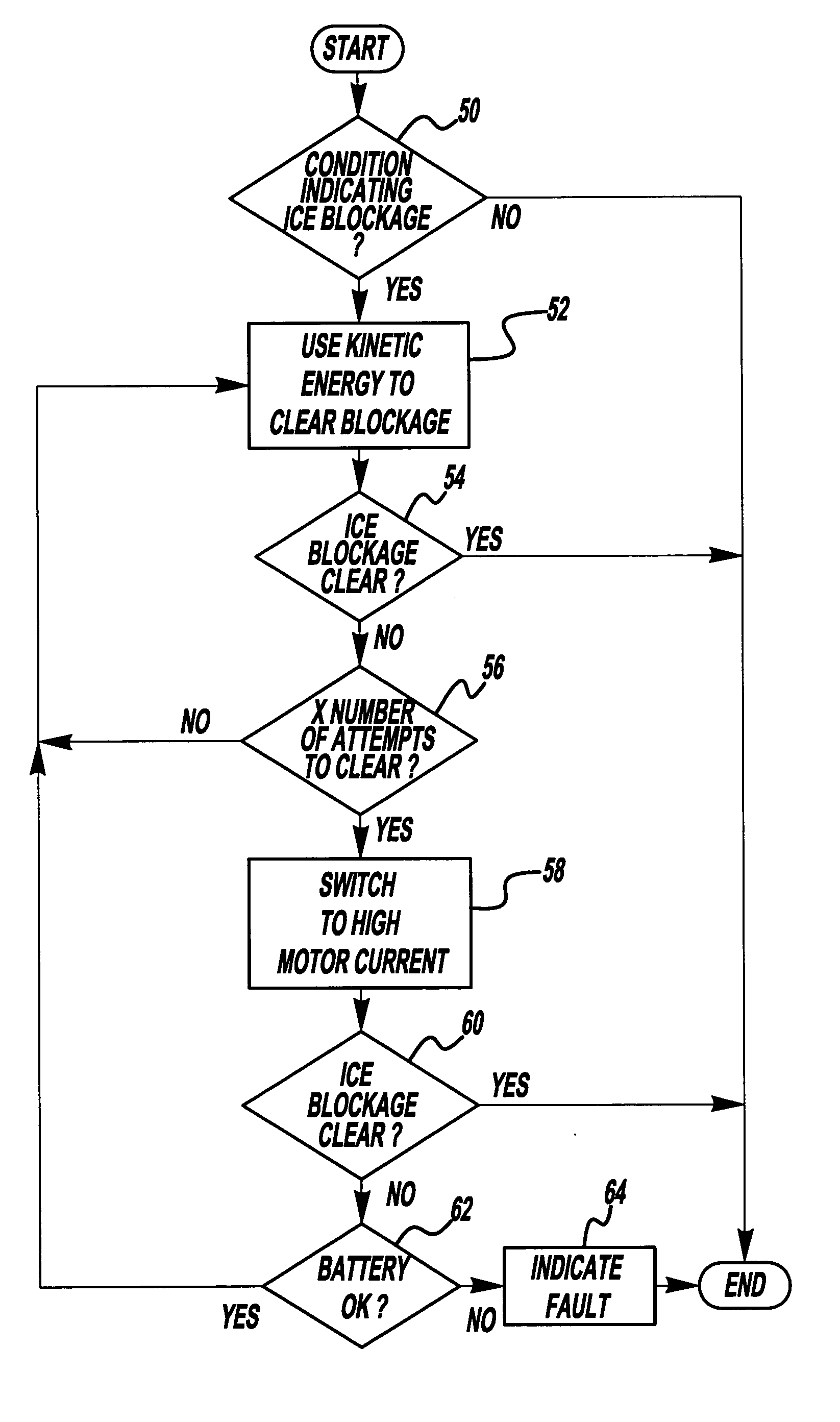
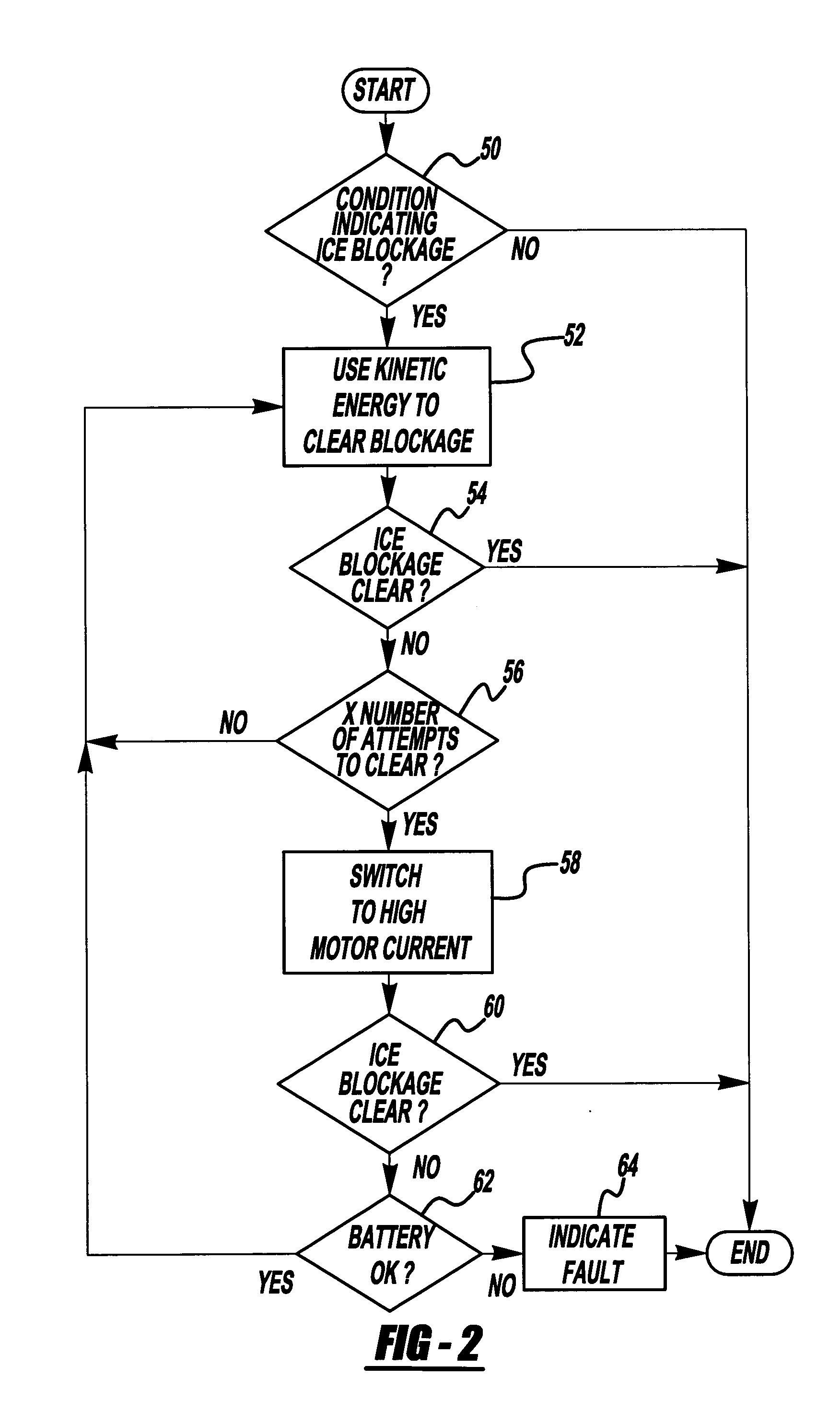
[0005] The present invention is a method and apparatus to remove ice or snow blockage from a throttle body. The present invention utilizes the heat that is generated by an electric motor in an ETC system to melt or soften the ice that is creating a blockage in the throttle body. In the preferred embodiment, when an ice blockage occurs the electric motor / throttle plate may not be able to move causing the control method of the present invention to increase the duty cycle for the current provided to the electric motor. The current in conjunction with the resistance of the electric motor coils will generate heat according to I2R heating losses, where I is the current provided to the electric motor and R is the electrical resistance of the coils of the electric motor. In alternate embodiment of the present invention, kinetic energy provided by the mechanical “striking” of the throttle plate, singly or in combination, with the heat provided by the electric motor may be used to clear a throttle body.

Problems solved by technology

Under certain environmental and operating conditions moisture in a solid state (ice or snow) may build up in the throttle body, impeding the rotation of a throttle plate.
As the throttle plate directly controls the power output of an engine any impediment to the movement of the throttle plate will affect the performance of the engine.

Method used


Image

  • Electronic throttle ice break method and apparatus
  • Electronic throttle ice break method and apparatus
  • Electronic throttle ice break method and apparatus

Examples


Embodiment Construction

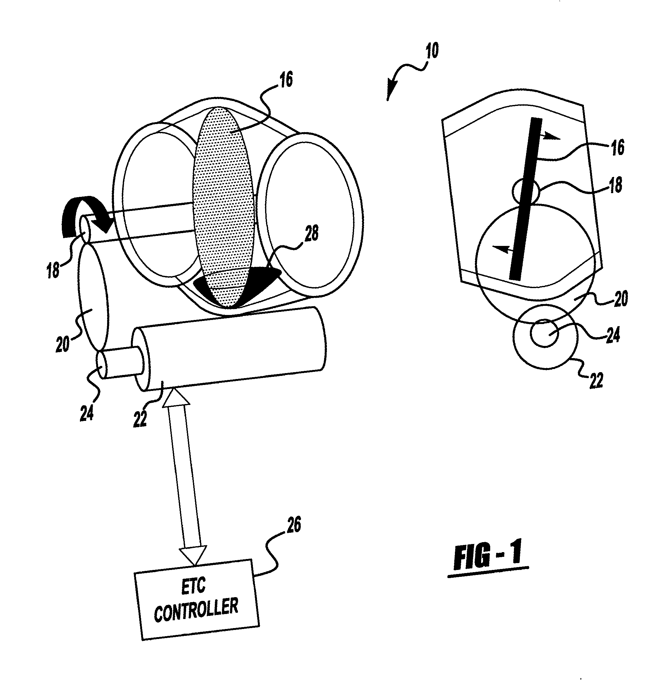
[0010] Referring to FIG. 1, an ETC throttle body 10 is shown. The throttle body 10 includes a throttle plate of blade 16, a rotational shaft 18 coupled to the throttle plate 16, a gear set arrangement 20, and an electric motor 22 having an output shaft 24. The electric motor 22 is controlled by a stand alone ETC system 26, or in alternate embodiments is integrated into a standard vehicle controller such as a powertrain controller or body controller. The electric motor 22 may comprise any electric motor technology including, but not limited to, DC motors, AC motors, induction motors, permanent magnet brushless motors, stepper motors, and synchronous motors.

[0011] During the operation of the throttle body, the ETC controller 26 will provide a position command to the electric motor 22 and the electric motor 22 will provide position and speed feedback to the ETC controller 26. Position and speed feedback may be provided by a resolver, a potentiometer, a rotary voltage displacement tran...


PUM


Abstract

A method and apparatus for removing an ice blockage from a throttle body comprising heating an electric motor in a throttle body to melt the ice blockage.

Description

TECHNICAL FIELD [0001] The present invention relates to control systems for internal combustion engines, and more particularly to control systems for an electronic throttle. BACKGROUND OF THE INVENTION [0002] An important facet of combustion engine control is the regulation of air flow into a cylinder by a throttle and accordingly the quantity of fuel delivered into the cylinder. In an internal combustion engine (ICE) a throttle, having a movable throttle plate, directly regulates the power produced by the ICE at any operating condition by regulating the air flow into the ICE. The throttle plate is positioned to increase or decrease air flow into the ICE. The ICE acts as an air pump with the mass flow rate of air entering the ICE varying directly with throttle plate angular position. For any given fuel-air mixture, the power produced by the ICE is directly proportional to the mass flow rate of air into the ICE controlled by the throttle plate position. [0003] Electronic throttle con...

Claims


Application Information

Patent Timeline
Patent Type & Authority Applications(United States)
IPC IPC(8): F02D11/10
CPCF02D2011/108F02D11/107
Inventor VALASCHO, TYRUS J.BAUERLE, PAUL A.
Owner GENERAL MOTORS COMPANY
Learn More