Noise filter

a noise filter and filter body technology, applied in the field of noise filters, can solve the problems of noise filters using reflection loss as carried out in the related art, difficult to be used, complex structure, etc., and achieve the effects of reducing the dc resistance of the transmission line, reducing the overall thickness of the noise filter, and reducing the siz

Inactive Publication Date: 2006-08-15
MURATA MFG CO LTD
View PDF38 Cites 5 Cited by
  • Summary
  • Abstract
  • Description
  • Claims
  • Application Information

AI Technical Summary

Benefits of technology

[0038]Accordingly, the overall thickness of the noise filter can be reduced, and the size can be decreased. Moreover, the thickness of the transmission line can be set to be larger than that of the ground conductor. Thus, the DC resistance of the transmission line can be reduced, and larger current can be flown.

Problems solved by technology

In the case where a noise filter is disposed, e.g., in a line connecting circuits to each other, problems are caused in that probably, noise having a specific frequency resonates between the noise filter and a circuit in the periphery thereof, and the resonance causes amplification of the noise.
Accordingly, for electronic parts of which the signal frequencies exceed 100 MHz, noise filters using reflection loss as carried out in the related art ones are difficult to be used.
The structure is complicated, the size can be reduced with much difficulty, and the manufacturing cost is high.
Moreover, problematically, the noise filter is difficult to be fixed to a printed wiring, since the filter has no chip-shape.

Method used


Image

  • Noise filter
  • Noise filter
  • Noise filter

Examples


first embodiment

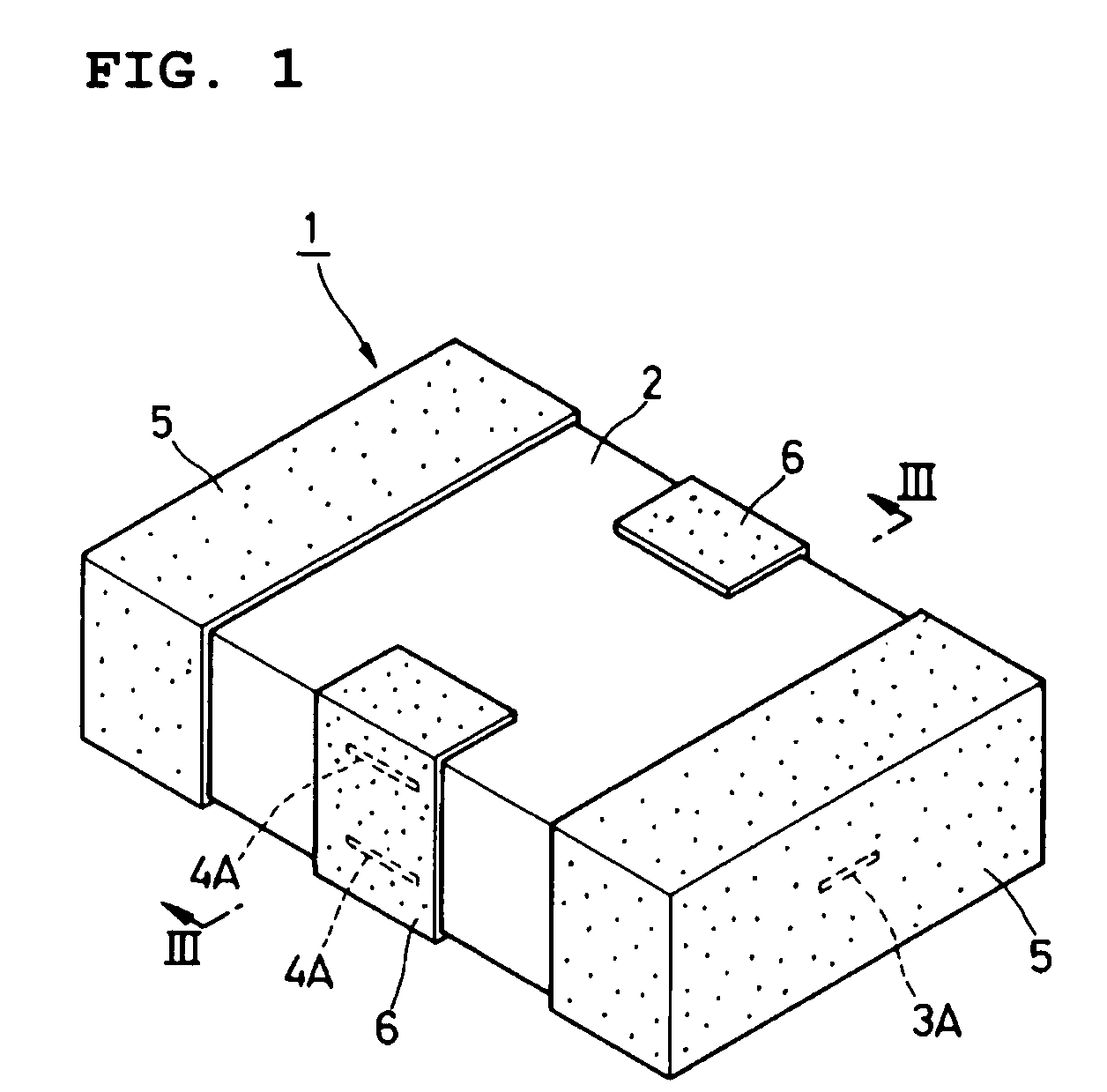
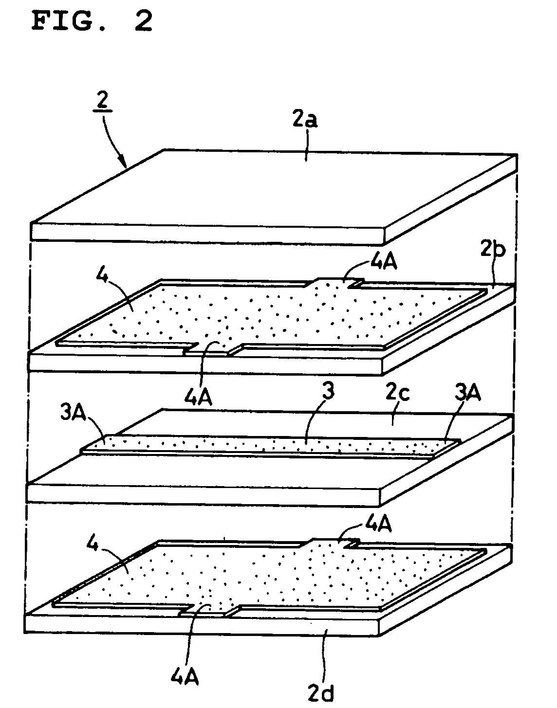
[0064]FIGS. 1 to 5 deal with the Reference numeral 1 designates a noise filter according to this embodiment. The noise filter 1 comprises magnetic sheets 2a to 2d which will be described later, a transmission line 3, ground conductors 4, signal electrodes 5, and a ground electrode 6. Moreover, the cut-off frequency fc of the noise filter 1 is set at a value e.g., within the range of 200 MHz to 2 GHz (200 MHz≦fc≦2 GHz).

[0065]A laminate 2 has a substantially rectangular column shape which constitutes the outline of the noise filter 1. The laminate 2 is formed by pressing of, e.g., four magnetic sheets 2a to 2d laid on each other and then firing these magnetic sheets 2a to 2d. Moreover, the magnetic sheets 2a to 2d are formed in a quadrangular sheet shape, respectively, and are made of a ceramic material having a magnetic characteristic such as ferrite or the like. The relative permeability of the magnetic sheets 2b and 2c sandwiched by the two ground conductors 4 which will be descri...

second embodiment

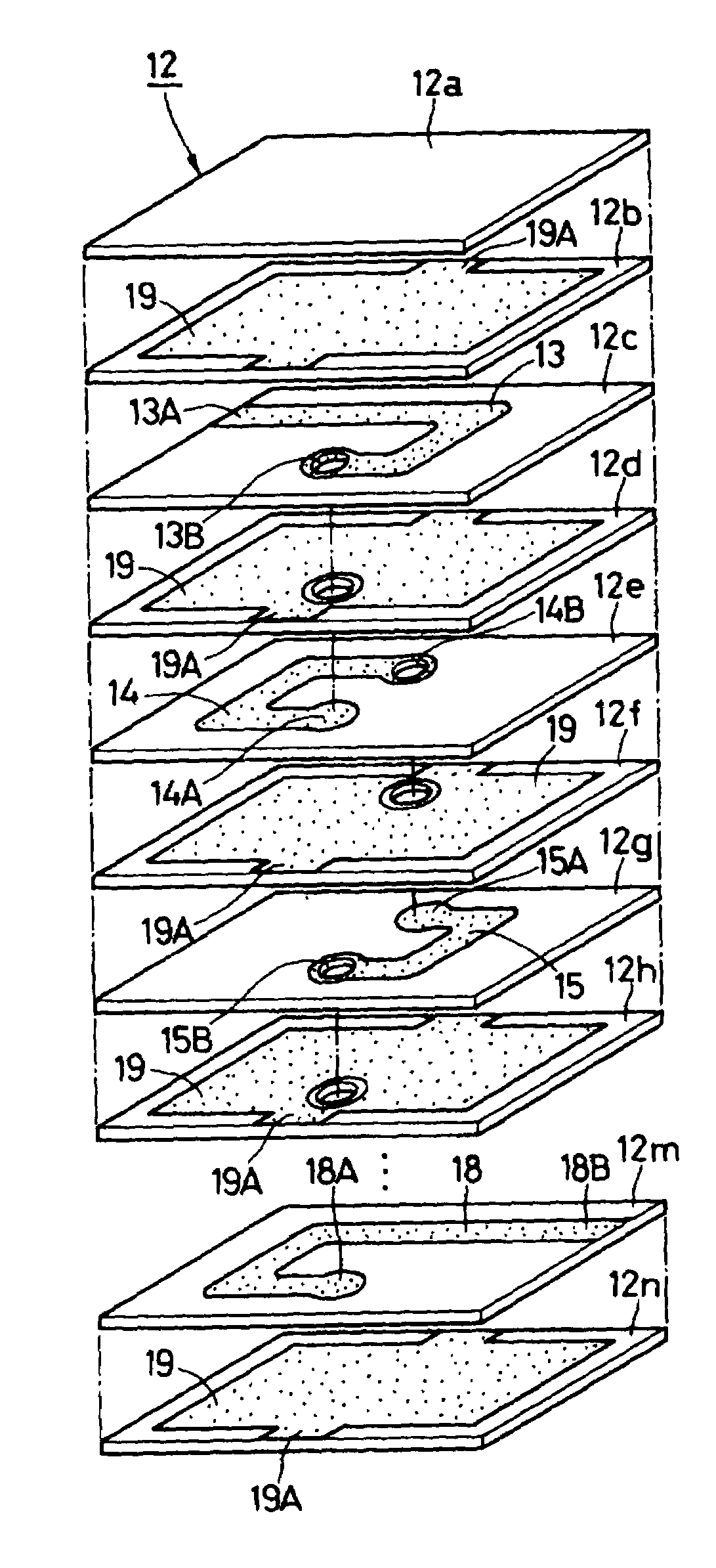
[0104]FIGS. 12 to 15 show a noise filter according to the present invention. Characteristically, the noise filter of this embodiment has a configuration in which transmission lines and ground conductors are alternately laminated in such a manner that the uppermost and lowermost layers of the magnetic sheets contain ground conductors, respectively.

[0105]A noise filter 11 comprises below-described magnetic sheets 12a to 12n, transmission lines 13 to 18, ground conductors 19, passing-through lines 20 to 24, signal electrodes 25, and ground electrodes 26.

[0106]The laminate 12 has a substantially prism-shape which constitutes the outline of the noise filter 11. The laminate 12 is formed by overlaying, e.g., fourteen magnetic sheets 12a to 12n, pressing them in the laminated state, and firing these magnetic sheets 12a to 12n. Each of the magnetic sheets 12a to 12n is formed in a substantially quadrangular 10 sheet shape, and for example, is formed with a ceramic material having a magnetic...

third embodiment

[0123]FIGS. 17 and 18 show a noise filter according to the present invention. Characteristically, in the noise filter of this embodiment, first and second transmission lines are provided on the same layer between magnetic sheets. First transmission lines and second transmission lines, and magnetic sheets are alternately overlaid, so that the plural first transmission lines are connected in series with each other, and moreover, the plural second transmission lines are connected in series with each other, independently of the first transmission lines.

[0124]A noise filter 31 comprises magnetic sheets 32a to 32j, first transmission lines 33 to 36, second transmission lines 37 to 40, ground conductors 41, passing-through lines (not shown), first signal electrodes 42, second signal electrodes 43, and ground conductors 44, which will be described below.

[0125]The laminate 32 has a substantially prism shape, which defines the outline of the noise filter 31. The laminate 32 is formed by lamin...


PUM

PropertyMeasurementUnit
frequenciesaaaaaaaaaa
cut-off frequenciesaaaaaaaaaa
frequencyaaaaaaaaaa

Abstract

A noise filter in which the resonance of noise can be prevented, which is small in size and inexpensive, and is useful especially in an electronic device of which the signal frequency exceeds 100 MHz. In the noise filter, ground conductors are arranged on the outermost layers of a laminate formed by lamination of magnetic sheets and firing thereof. Transmission lines and ground conductors are alternately arranged with the magnetic sheets being sandwiched between them, respectively. Signal electrodes connected to the transmission lines and ground electrodes connected to the ground conductors are formed on the outer surface of the laminate. Thus, a signal is transmitted through the transmission lines while the ground conductors are grounded, and therefore, high frequency noise can be attenuated by utilization of heat loss caused by the magnetic sheets.

Description

[0001]This application is a 371 of PCT / JP02 / 05864 filed on Jun. 12, 2002.BACKGROUND OF THE INVENTION[0002]1. Field of the Invention[0003]The present invention relates to a noise filter which is suitable for use in suppression of electromagnetic noise interferences in electronic devices.[0004]2. Description of the Related Art[0005]In general, various types of noise filters are used in suppression of electromagnetic noise interferences in electronic devices. In a known related art noise filter, for example, a circuit using a lumped constant such as a three-terminal capacitor is formed (see for example, Japanese Unexamined Patent Application Publication No. 10-154632 ). In such a noise filter of the related art, noise is suppressed using a reflection loss in which the reflection coefficient is increased at the frequency of noise to be generated.[0006]Moreover, in a known noise filter according to another related art, a circuit including many inductors and capacitors is formed (see for ...

Claims


Application Information

Patent Timeline
Patent Type & Authority Patents(United States)
IPC IPC(8): H03H7/00H01F17/00H01F27/28H03H1/00
CPCH01F17/0013H03H1/0007H01F27/2804H01F2017/0026H01F2017/0073H03H9/00
Inventor YAMAMOTO, HIDETOSHIUCHIDA, KATSUYUKIISHIDA, KOUSUKE
Owner MURATA MFG CO LTD
Why Eureka
Try Eureka