
Solid filling tank

a filling tank and solid technology, applied in the direction of indirect heat exchangers, lighting and heating apparatus, separation processes, etc., can solve the problems of reducing the heat exchange performance between generating excess stress locally, and reducing the heat exchange performance of the hydrogen absorbing alloy powder and the heat exchanger. , to achieve the effect of rationally avoiding the problems of conventional technology and lowering the heat exchange performan

Inactive Publication Date: 2005-03-10
TOYOTA IND CORP +1
View PDF12 Cites 23 Cited by
  • Summary
  • Abstract
  • Description
  • Claims
  • Application Information

AI Technical Summary

Benefits of technology

[0009] It is an object of the present invention to provide a technology that is useful to surely prevent movement of solid particles being filled in a solid filling tank without lowering the heat exchanging performance between the solid particles and a heat exchanger, in a solid filling tank in which the heat exchanger is fitted in a tank main body of the solid filling tank in which the solid particles capable of absorbing or adsorbing a predetermined gas are filled.

Problems solved by technology

Therefore, when the filled hydrogen absorbing alloy powders absorb hydrogen in a state subsided and consolidated in the storage tank, in some cases, an excessive stress is locally generated against a tank main body due to the expansion of the hydrogen absorbing alloy and the stress influences on a tank main body of the storage tank or on a lining member disposed in the storage tank.
However, extra space to provide an extra member such as the sheet member is needed in the tank main body of the storage tank.
Therefore, in the first technology, the subsidence of the hydrogen absorbing alloy powders in the tank can be prevented, whereas reduction in the heat exchanging performance between the hydrogen absorbing alloy powders and the heat exchanger becomes a problem.
Nevertheless, there is the limit to prevent the subsidence of the hydrogen absorbing alloy powders since the cooling / heating medium tube has the R portion (curved portion).
Therefore, it is hard to say that the second technology is the exact approach.

Method used

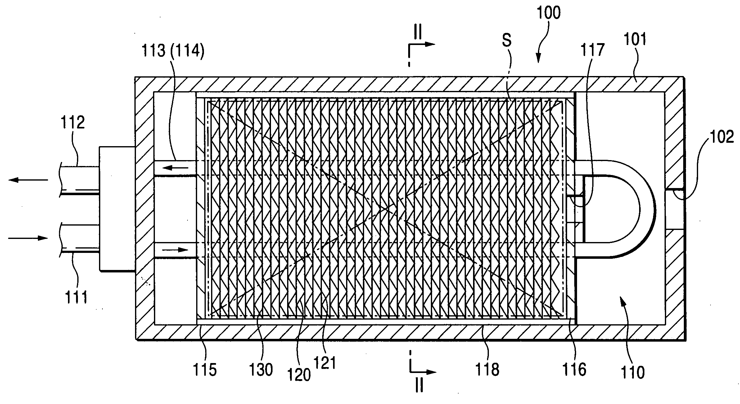
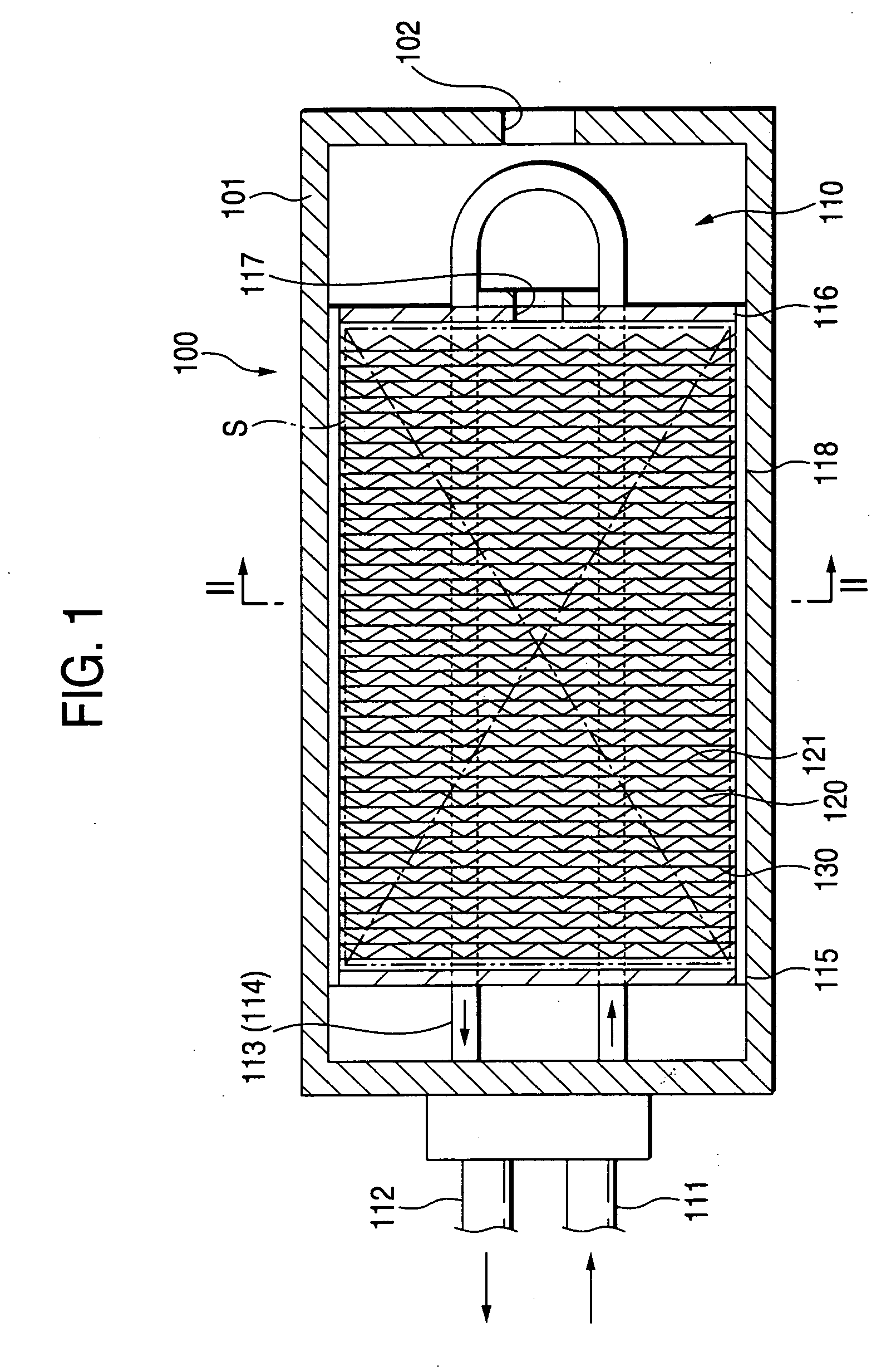

Image

  • Solid filling tank
  • Solid filling tank
  • Solid filling tank

Examples


Embodiment Construction

[0020] Hereinafter, prior to describing the preferred embodiments according to the invention, various aspects of the invention will be described in detail.

[0021] The present invention provides a technology that, since movement of solid particles capable of absorbing or adsorbing a predetermined gas is restricted by a plurality of heat-transferring fins constituting a heat exchanger disposed in a solid filling tank, the movement of the solid particles filled in the solid filling tank can be prevented from the heat exchanging performance between the solid particles and the heat exchanger to be lowered. The present invention is not simply limited to the technology to provide a restricting portion for restricting the movement of the solid particles to a tank main body of the solid filling tank. The present invention can implement a rational technology to construct a solid filling tank, which is not easily thought of from the conventional technology, having a heat-transferring fins, whi...


PUM


Abstract

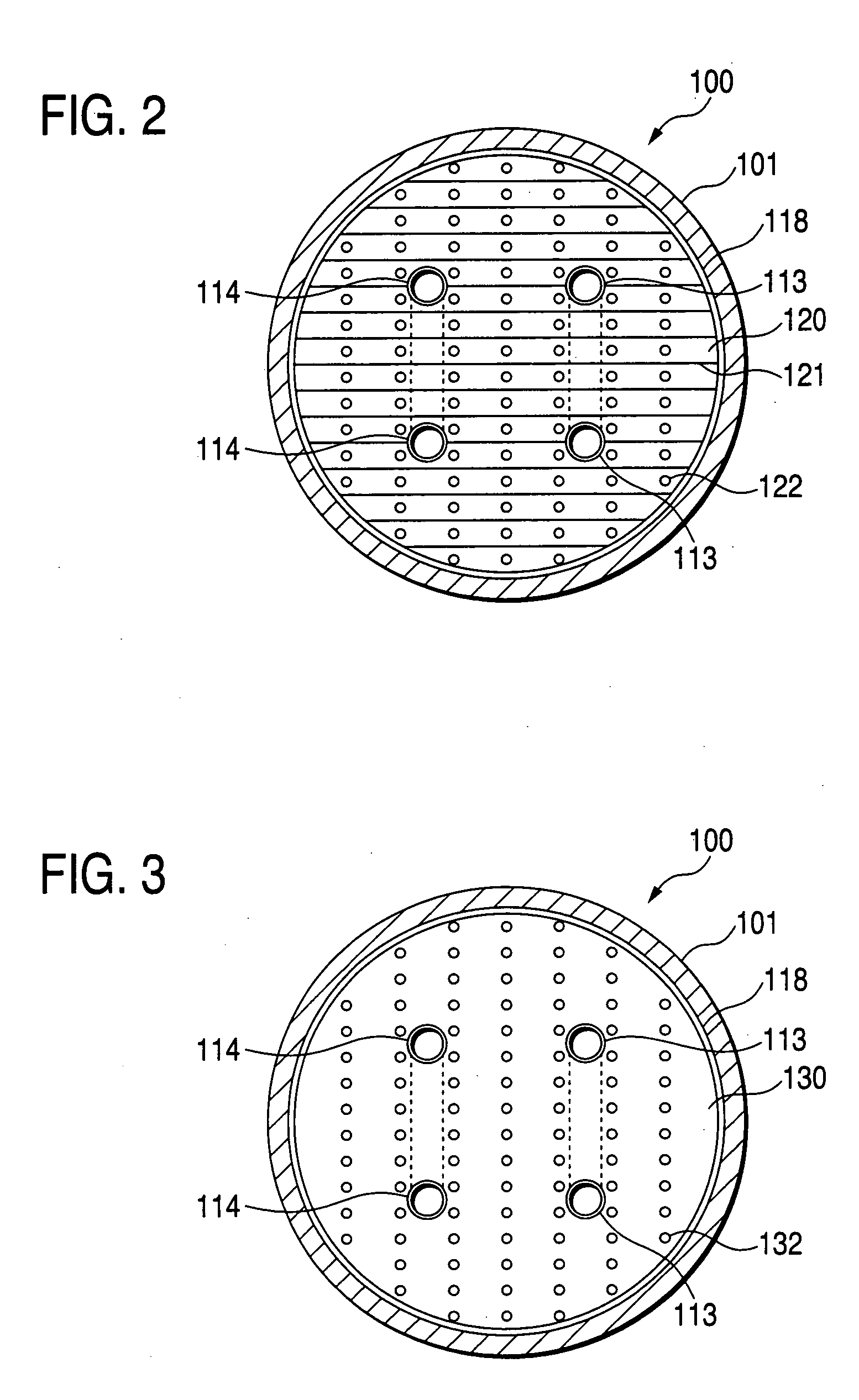
In a hydrogen storing tank (solid filling tank) in which a hydrogen absorbing alloy (solid) is filled, a heat exchanger for executing heat exchange with the hydrogen absorbing alloy is constructed by laminating alternately a first heat-transferring fins formed in corrugated plate shape and a second heat-transferring fins formed in flat plate shape. Partitioned portions that are partitioned by the first heat-transferring fins and the second heat-transferring fins restrict movement of hydrogen absorbing alloy powders (MH powders) in a subsiding direction. Therefore, movement of the MH powders can surely be prevented by not using members that has no concern with the heat exchange and reduces an amount of filled MH powders and a volume in which the heat exchanger is provided.

Description

BACKGROUND OF THE INVENTION [0001] 1. Field of the Invention [0002] The present invention relates to a solid filling tank in which solid particles capable of absorbing or adsorbing a gas such as a hydrogen gas, are filled. [0003] 2. Description of the Related Art [0004] As well as heat of solar light, there is given a great attention to hydrogen as clean energy source. Especially in developing a fuel system for a hydrogen fuel cell vehicle, attention is focused on a technology to effectively store and discharge hydrogen by utilizing a hydrogen absorbing alloy that absorbs hydrogen. As for a particular example of such technology, there is known a technology to fill hydrogen absorbing alloy powders in a storage tank (hydrogen storage tank), and to cause the hydrogen absorbing alloy powders in the storage tank to absorb and store the hydrogen and to discharge for utilizing the hydrogen. The hydrogen absorbing alloy has the characteristic that generates heat when absorbing hydrogen and ...

Claims


Application Information

Patent Timeline
IPC IPC(8): C01B3/00F17C11/00F28D20/00F28F1/32
CPCC01B3/0005F17C11/005F28D7/06Y02E60/327F28F1/32Y02E60/321F28D2021/0047Y02E60/32
Inventor FUJITA, KATSUYOSHIKUBO, HIDEHITOTOH, KEIJIKUMANO, AKIKOMORI, DAIGORO
Owner TOYOTA IND CORP
Learn More