Composite leaf spring having an arcuate attachment arrangement for vehicle mounting

a technology of composite leaf springs and vehicle frame rails, which is applied in the direction of springs/dampers, mechanical equipment, transportation and packaging, etc., can solve the problems of reducing the physical characteristics of the spring, affecting the performance of the spring, so as to avoid dissimilar material wear points and lighten the weight

Inactive Publication Date: 2005-03-10
ARVINMERITOR TECH
View PDF25 Cites 33 Cited by
  • Summary
  • Abstract
  • Description
  • Claims
  • Application Information

AI Technical Summary

Benefits of technology

[0013] The present invention therefore provides an uncomplicated composite leaf spring attachment arrangement which accommodates various suspension members, does not require through apertures, avoids dissimilar material wear points, and is light in weight.

Problems solved by technology

Steel leaf springs may be disadvantageous because they are relatively heavy, noisy, and subject to corrosion.
Although providing many benefits including lightweight and great strength, attachment of fiber reinforced resin composite leaf springs to the vehicle frame rails may pose various difficulties.
One difficulty includes the preference for avoiding mounting arrangements that require locating apertures through the composite leaf spring.
Penetration of the composite leaf spring severs the fibrous materials and correspondingly reduces the physical characteristics of the spring.
Conversely, elimination or minimization of apertures further decreases the mounting versatility for particular vehicle designs as specific metal end sections are utilized from frame rail mounting.
That is, each leaf spring must be specifically tailored to a specific vehicle which may decrease the versatility of each leaf spring.
Disadvantageously, the bracket arrangement may be relatively heavy in weight which may offset some of the weight advantage inherent to composite materials.
These dissimilar material interfaces are wear points which may weaken the composite material and reduce the life of the suspension.

Method used


Image

  • Composite leaf spring having an arcuate attachment arrangement for vehicle mounting
  • Composite leaf spring having an arcuate attachment arrangement for vehicle mounting
  • Composite leaf spring having an arcuate attachment arrangement for vehicle mounting

Examples


Embodiment Construction

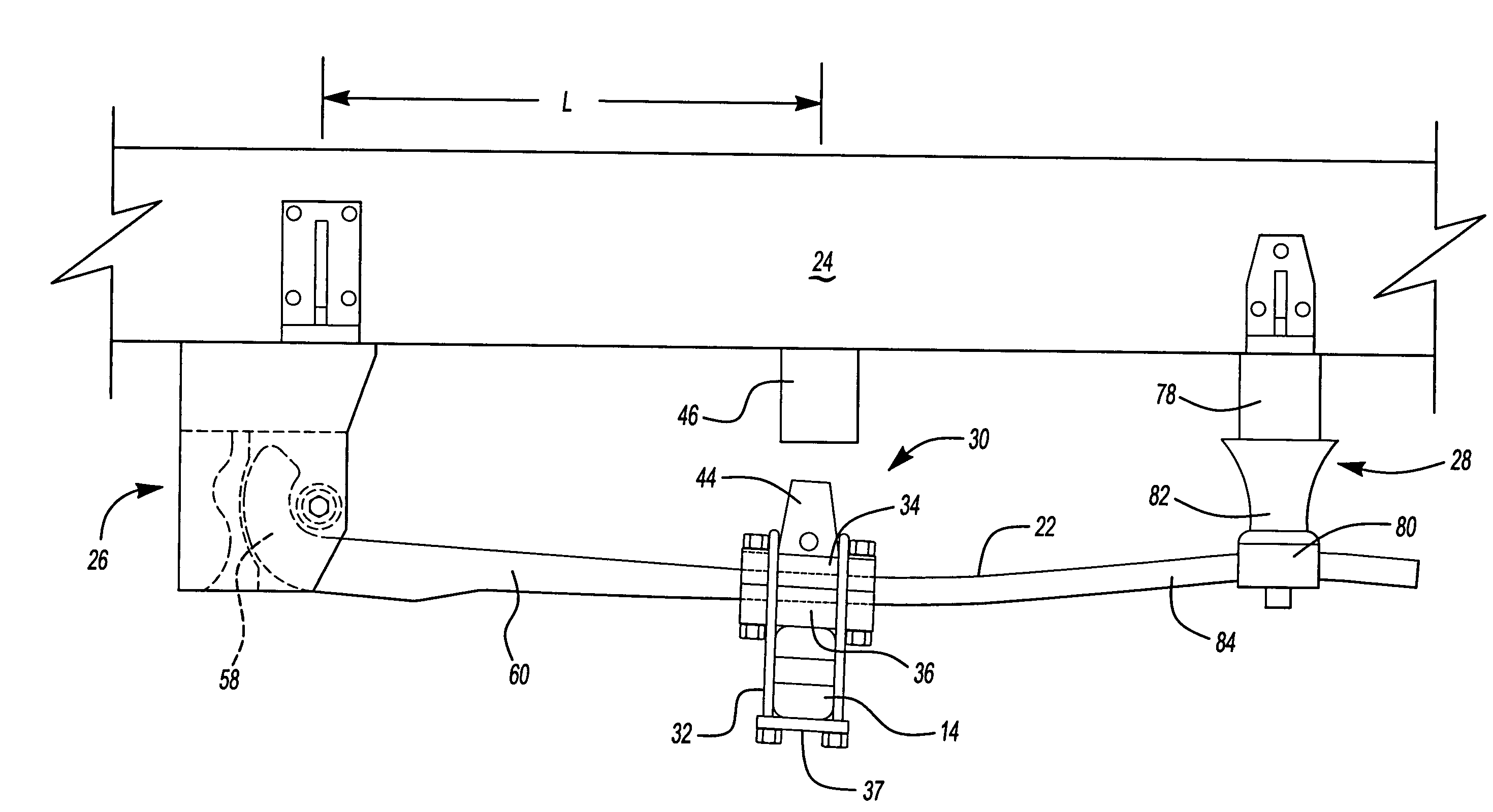
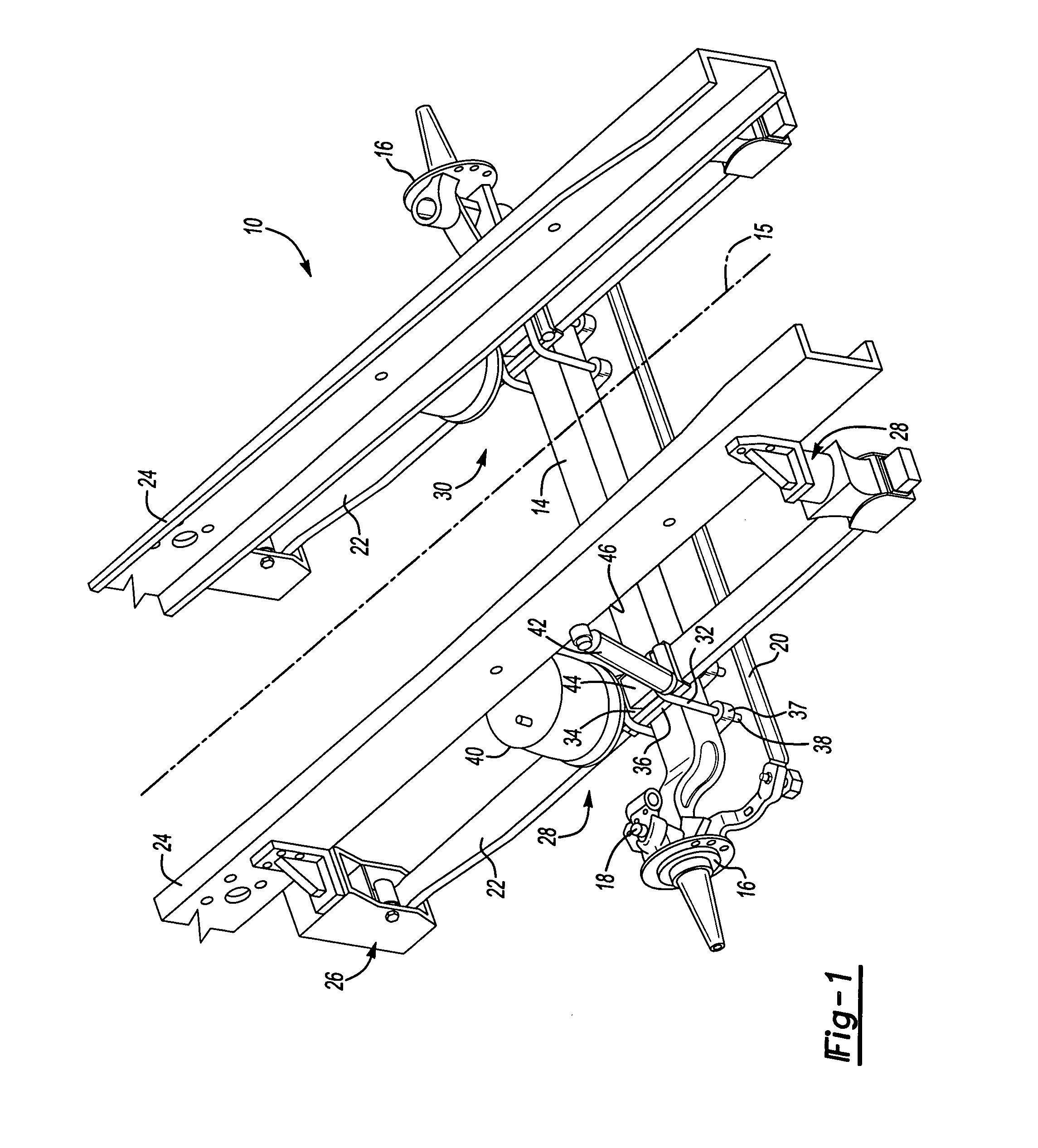
[0028]FIG. 1 illustrates a general perspective view of a steerable air spring suspension system 10. Although a steerable air spring suspension is disclosed in the illustrated embodiment, it should be understood that other suspensions will benefit from the present invention. The present invention is particularly applicable to relatively heavy commercial vehicles.

[0029] The system 10 generally includes a primary structural support such as an axle beam 14. The axle beam 14 is preferably a single hollow square beam located transverse to a vehicle longitudinal axis 15. A pair of steerable hub assemblies 16 are pivotally supported by the axle beam 14. A king pin 18 or similar member pivotally attaches the steerable hub assembly 16 to the axle beam 14 in a known manner. The steerable hub assemblies 16 are articulatable through a steering gear assembly (not shown) and are linked together by a linkage 20.

[0030] To dampen movement of the axle beam 14, a flexible member such as a composite l...


PUM

PropertyMeasurementUnit
depthaaaaaaaaaa
widthaaaaaaaaaa
cross-sectional areaaaaaaaaaaa

Abstract

A suspension system includes a composite leaf spring having an arcuate segment that is located between a retaining pin and a bumper. The retaining pin includes a shank surrounded by a resilient tube. The bumper is located adjacent a rear wall of the bracket opposite the retaining pin. The bumper includes an arcuate face to engage the outer arc of the arcuate segment while the pin is at least partially surrounded by the arcuate segment. The end of the composite leaf spring is thereby securely yet resiliently retained within the front leaf spring attachment system without penetrating fasteners.

Description

BACKGROUND OF THE INVENTION [0001] The present invention relates to a leaf spring suspension and, more particularly, to a composite leaf spring defining an arcuate segment for mounting the leaf spring to a vehicle mainframe. [0002] Various conventional vehicle suspensions include a leaf spring fabricated from a series of superimposed steel leaves. Steel leaf springs may be disadvantageous because they are relatively heavy, noisy, and subject to corrosion. [0003] More recently, fiber reinforced resin composite materials have been utilized as a substitute for steel leaf springs. In some leaf springs of this type, a curved central section of the spring is molded from longitudinally extending fibrous material impregnated with a thermosetting resin. Separate metal end sections are attached through mechanical connectors to the ends of the curved central section. Another form of fiber reinforced resin composite leaf spring includes continuous strands of fibrous material impregnated with a ...

Claims


Application Information

Patent Timeline
Patent Type & Authority Applications(United States)
IPC IPC(8): B60G7/04B60G11/10B60G11/46F16F1/368
CPCB60G7/04B60G11/10B60G11/465B60G2202/112B60G2204/121F16F1/3683B60G2204/4306B60G2206/601B60G2206/72B60G2206/81022B60G2204/4232
Inventor PLATNER, DAVID K.REZAKHANLOU, RAMINTROTTER, JAMES
Owner ARVINMERITOR TECH
Why Eureka
Try Eureka